Revision notes for Edexcel A Level Physics Series and parallel circuits. Open the guide for explanations and worked examples. Written against the Edexcel A Level Physics (9PH0) specification, so the content matches what's examinable rather than general Physics background.
Series and parallel circuits
What you'll learn
- How current, potential difference and resistance behave in series and parallel circuits.
- How Kirchhoff’s laws explain the “rules” for circuit calculations.
- How to find the equivalent resistance of a network.
- How to tackle mixed circuits step by step without getting lost.
Before you start: the key electrical quantities
A circuit calculation usually comes down to tracking three quantities: current, potential difference, and resistance.
Definition
Current, potential difference and resistance
- Electric current, III, is the rate of flow of charge:
It is measured in amperes, A.
- Potential difference, VVV, is the energy transferred per unit charge between two points:
It is measured in volts, V.
- Resistance, RRR, is the opposition a component gives to current:
It is measured in ohms, Ω.
Conventional current is taken to flow from the positive terminal of a supply around the circuit to the negative terminal. Electrons actually drift the opposite way, but conventional current is what you use in circuit diagrams and calculations.
Example
Finding current and resistance
A charge of 18 C passes through a component in 6.0 s. The potential difference across the component is 12 V. Find the current and resistance.
- Use the definition of current:
- Use R=V/IR = V/IR=V/I for the component:
- Check the units: volts per ampere is ohms, so the resistance is 4.0 Ω.
Nodes, branches and loops
A node is a point where wires join. In ideal circuit diagrams, any points connected by a plain wire are treated as being at the same potential.
A branch is one possible path through part of a circuit. A loop is a complete closed path that charge can travel around.
These words matter because series and parallel circuits are really about how components are connected between nodes.
Kirchhoff’s laws: the reason the rules work
The rules for series and parallel circuits are not random facts to memorise. They come from conservation laws.
Key Idea
Kirchhoff’s laws
- Kirchhoff’s first law: at a junction, the total current entering equals the total current leaving. This is conservation of charge.
- Kirchhoff’s second law: around a closed loop, the total electromotive force equals the total potential difference across the components. This is conservation of energy.
Example
Using the junction rule
A current of 0.75 A reaches a junction. One branch carries 0.20 A. Find the current in the other branch.
- Apply Kirchhoff’s first law: current into the junction equals current out of the junction.
- Set up the equation:
- Rearrange:
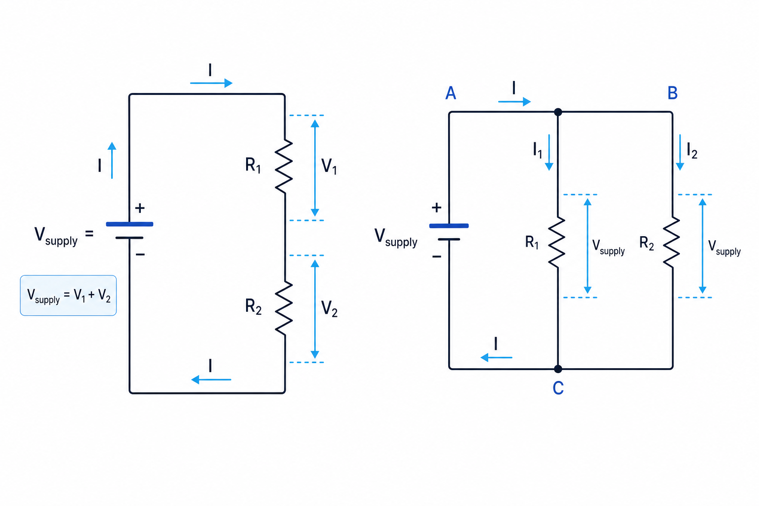
The key visual difference is that a series circuit has only one path for current, while a parallel circuit has more than one path.
Series circuits
Definition
Series circuit
Components are in series when they are connected one after another in a single path, so the same current passes through each component.
In a series circuit:
- The current is the same everywhere in the loop.
- The supply potential difference is shared between the components.
- The total resistance is the sum of the individual resistances.
For resistors in series:
Rtotal=R1+R2+R3+… R_\text{total} = R_1 + R_2 + R_3 + \dots Rtotal=R1+R2+R3+…The potential difference across each resistor depends on its resistance. A larger resistance gets a larger share of the supply potential difference because V=IRV = IRV=IR, and the current is the same through each resistor.
Example
Calculating values in a series circuit
A 12 V supply is connected to a 4.0 Ω resistor and a 6.0 Ω resistor in series. Find the current and the potential difference across each resistor.
- Add the resistances because the resistors are in series:
- Use I=V/RI = V/RI=V/R to find the current from the supply:
- Use V=IRV = IRV=IR for the 4.0 Ω resistor:
- Use V=IRV = IRV=IR for the 6.0 Ω resistor:
- Check using Kirchhoff’s second law:
Common Mistake
Giving every series component the full supply voltage
In series, the supply potential difference is split between components. Only the total around the loop equals the supply potential difference.
Parallel circuits
Definition
Parallel circuit
Components are in parallel when each component is connected across the same two nodes, so each branch has the same potential difference across it.
In a parallel circuit:
- The potential difference across each branch is the same.
- The current splits at junctions.
- The total current is the sum of the branch currents.
- The total resistance is less than the smallest individual branch resistance.
For resistors in parallel:
1Rtotal=1R1+1R2+1R3+… \frac{1}{R_\text{total}} = \frac{1}{R_1} + \frac{1}{R_2} + \frac{1}{R_3} + \dots Rtotal1=R11+R21+R31+…This happens because adding another parallel branch gives charge an extra path to flow through, so the circuit draws more current for the same supply potential difference.
Example
Calculating values in a parallel circuit
A 12 V supply is connected across two parallel resistors: 6.0 Ω and 3.0 Ω. Find the branch currents, total current and equivalent resistance.
-
In parallel, each branch has the full supply potential difference, so each resistor has 12 V across it.
-
Find the current through the 6.0 Ω resistor:
- Find the current through the 3.0 Ω resistor:
- Add the branch currents:
- Use R=V/IR = V/IR=V/I for the whole network:
Tip
Quick check for parallel resistors
For resistors in parallel, the equivalent resistance must be smaller than the smallest branch resistance. For two resistors only, you can use Rtotal=R1R2R1+R2R_\text{total} = \frac{R_1R_2}{R_1 + R_2}Rtotal=R1+R2R1R2.
Common Mistake
Adding parallel resistors like series
In parallel, you do not calculate RtotalR_\text{total}Rtotal by adding the resistances. You add the reciprocals, sometimes called conductances, where conductance means 1/R1/R1/R.
Mixed series-parallel circuits
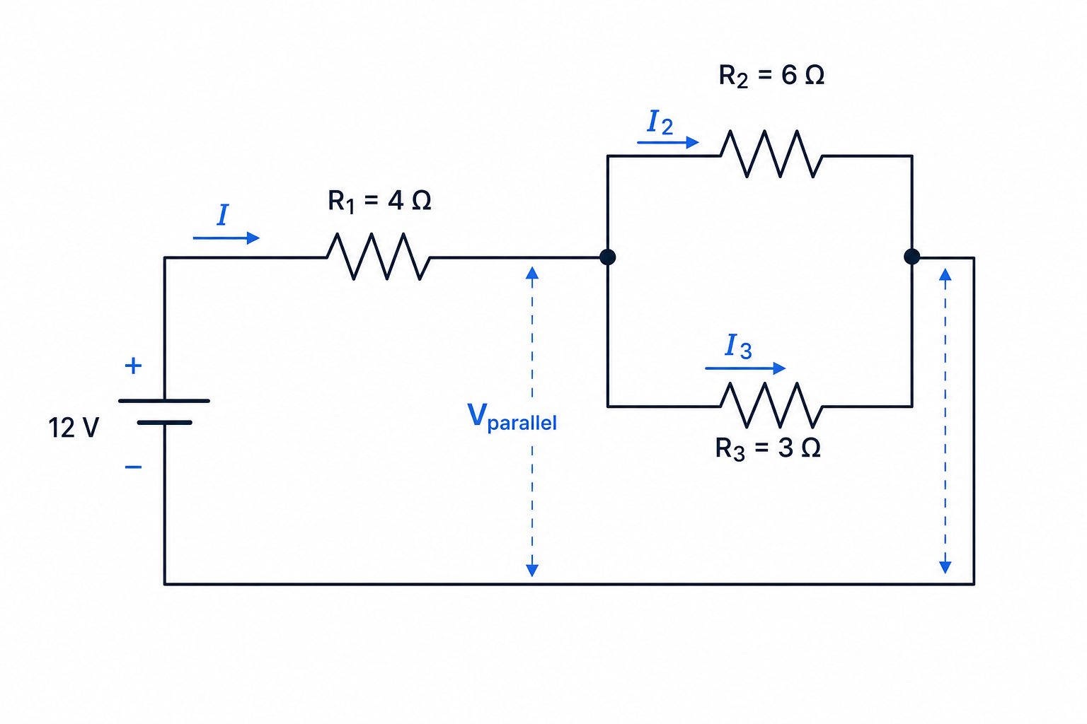
Many exam questions use a mixture of series and parallel parts. The safest method is to reduce the circuit in stages, replacing each obvious group with its equivalent resistance.
Example
Solving a mixed resistor network
In the circuit shown, a 12 V supply is connected to a 4.0 Ω resistor in series with a parallel combination of 6.0 Ω and 3.0 Ω. Find the total current and the branch currents.
- First reduce the parallel part:
- Now add the series resistor:
- Find the total current from the supply:
- Find the potential difference across the 4.0 Ω resistor:
- Use energy conservation to find the potential difference across the parallel section:
- Use the same parallel voltage for each branch:
- Check the branch currents add to the total current:
Power in series and parallel circuits
Electrical power is the rate of energy transfer. For a component:
P=VI=I2R P = VI = I^2R P=VI=I2RIn series, the current is the same through each component, so a larger resistance dissipates more power because of P=I2RP = I^2RP=I2R.
In parallel, the potential difference is the same across each branch. Lower resistance branches take a larger current, so they often dissipate more power.
Measuring current and potential difference
An ammeter measures current and must be connected in series with the component whose current you want. A good ammeter has very low resistance so it changes the circuit as little as possible.
A voltmeter measures potential difference and must be connected in parallel across the component. A good voltmeter has very high resistance so it draws very little current.
Common Mistake
Putting meters in the wrong place
An ammeter goes in series because it measures the current passing through a component. A voltmeter goes in parallel because it compares the energy per charge at two points.
Common Mistake
Ideal supplies and real cells
The series and parallel rules still apply to the external circuit, but real cells have internal resistance. If internal resistance is included, use the terminal potential difference across the external network, not automatically the labelled emf.
Exam technique
In the exam
- Redraw the circuit if needed, marking nodes and identifying which components are truly in series or truly in parallel.
- Reduce resistor networks in stages, then work backwards to find currents and potential differences in individual components.
- Check your answer: series resistance should increase, parallel resistance should decrease, branch currents should add, and loop voltages should add to the supply.
Self review
Check yourself
- Why is the current the same through every component in a series circuit?
- Two resistors, 8.0 Ω and 12 Ω, are connected in parallel across a 6.0 V supply. What are the two branch currents?
- In a mixed circuit, why is it usually helpful to find the equivalent resistance first?