Revision notes for Edexcel A Level Physics Potential dividers and sensors. Open the guide for explanations and worked examples. Written against the Edexcel A Level Physics (9PH0) specification, so the content matches what's examinable rather than general Physics background.
Potential dividers and sensors
What you'll learn
- How a potential divider produces a chosen output voltage from a supply.
- How to calculate VoutV_\text{out}Vout using resistance ratios.
- How LDRs and thermistors can turn light or temperature changes into voltage changes.
- How to spot common exam traps, including the effect of a load.
Prerequisites: voltage, current and resistance
Before potential dividers, you need three circuit ideas.
Definition
Potential difference
Potential difference, or voltage, is the energy transferred per unit charge between two points in a circuit: V=W/QV = W/QV=W/Q. It is measured in volts, V.
Current is the rate of flow of charge, measured in amperes, A. Resistance is how much a component opposes current, measured in ohms, Ω. For an ohmic component:
R=VIR = \frac{V}{I}R=IVIn a series circuit, components are connected one after another in a single path. The same current flows through each component, but the supply voltage is shared between them.
Key Idea
Series voltage sharing
In series, the same current flows through every resistor, so the resistor with the larger resistance gets the larger share of the potential difference.
Example
Finding voltage shares in series
A 12.0 V supply is connected across two series resistors: 2.0 kΩ and 4.0 kΩ. Find the potential difference across each resistor.
-
Add the series resistances:
Rtotal=2.0 kΩ+4.0 kΩ=6.0 kΩR_\text{total} = 2.0\ \text{k}\Omega + 4.0\ \text{k}\Omega = 6.0\ \text{k}\OmegaRtotal=2.0 kΩ+4.0 kΩ=6.0 kΩ -
Calculate the current through the series chain:
I=VsRtotal=12.0 V6.0×103 Ω=2.0×10⁻³ AI = \frac{V_s}{R_\text{total}} = \frac{12.0\ \text{V}}{6.0 \times 10^3\ \Omega} = 2.0 \times 10^{-3}\ \text{A}I=RtotalVs=6.0×10³ Ω12.0 V=2.0×10⁻³ A -
Use V=IRV = IRV=IR for each resistor:
V1=(2.0×10⁻³ A)(2.0×10³ Ω)=4.0 VV_1 = (2.0 \times 10^{-3}\ \text{A})(2.0 \times 10^3\ \Omega) = 4.0\ \text{V}V1=(2.0×10⁻³ A)(2.0×10³ Ω)=4.0 V V2=(2.0×10⁻³ A)(4.0×10³ Ω)=8.0 VV_2 = (2.0 \times 10^{-3}\ \text{A})(4.0 \times 10^3\ \Omega) = 8.0\ \text{V}V2=(2.0×10⁻³ A)(4.0×10³ Ω)=8.0 V -
Check the shares add to the supply voltage:
4.0 V+8.0 V=12.0 V4.0\ \text{V} + 8.0\ \text{V} = 12.0\ \text{V}4.0 V+8.0 V=12.0 V
The potential divider
Definition
Potential divider
A potential divider is a series circuit used to produce an output voltage that is a fraction of the supply voltage.
Usually, two resistors are connected in series across a supply. The output voltage, VoutV_\text{out}Vout, is measured across one of the resistors. In the standard form below, VoutV_\text{out}Vout is taken across the lower resistor, R2R_2R2.
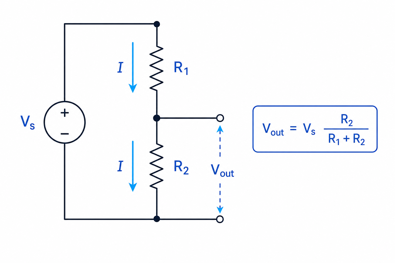
Because the resistors are in series, the current is:
I=VsR1+R2I = \frac{V_s}{R_1 + R_2}I=R1+R2VsThe output voltage is the potential difference across R2R_2R2:
Vout=IR2=VsR2R1+R2\begin{aligned} V_\text{out} &= IR_2 \\ &= V_s\frac{R_2}{R_1 + R_2} \end{aligned}Vout=IR2=VsR1+R2R2Key Idea
Potential divider equation
If the output is taken across the lower resistor, use Vout=VsR2R1+R2V_\text{out} = V_s\frac{R_2}{R_1 + R_2}Vout=VsR1+R2R2. The resistor across which you measure the output goes in the numerator.
Example
Calculating the output voltage
A 9.0 V supply is connected across two series resistors. The top resistor is 2.2 kΩ and the lower resistor is 3.3 kΩ. Find VoutV_\text{out}Vout across the lower resistor.
-
Identify the resistor across which the output is measured:
R2=3.3 kΩR_2 = 3.3\ \text{k}\OmegaR2=3.3 kΩ -
Substitute into the divider equation:
Vout=9.0 V×3.3 kΩ2.2 kΩ+3.3 kΩV_\text{out} = 9.0\ \text{V} \times \frac{3.3\ \text{k}\Omega}{2.2\ \text{k}\Omega + 3.3\ \text{k}\Omega}Vout=9.0 V×2.2 kΩ+3.3 kΩ3.3 kΩ -
Calculate the resistance fraction:
3.32.2+3.3=3.35.5=0.60\frac{3.3}{2.2 + 3.3} = \frac{3.3}{5.5} = 0.602.2+3.33.3=5.53.3=0.60 -
Find the output voltage:
Vout=9.0 V×0.60=5.4 VV_\text{out} = 9.0\ \text{V} \times 0.60 = 5.4\ \text{V}Vout=9.0 V×0.60=5.4 V
Common Mistake
Putting the wrong resistor on top
Do not automatically put the lower resistor in the numerator unless the output is actually measured across it. If VoutV_\text{out}Vout is across R1R_1R1, then R1R_1R1 goes in the numerator instead.
Adjustable potential dividers
A variable resistor has a resistance that can be changed. A potentiometer is a three-terminal variable resistor used as an adjustable potential divider. The middle contact, called the wiper, slides along the resistive track.
If a potentiometer is connected across a supply, the wiper can provide any output voltage from nearly zero up to the supply voltage.
Example
Using a potentiometer position
A 5.0 V supply is connected across a uniform potentiometer. The wiper is 40% of the way along the track from the 0 V end. Find the output voltage measured from the wiper to 0 V.
-
Treat the lower part of the track as 40% of the total resistance:
RlowerRtotal=0.40\frac{R_\text{lower}}{R_\text{total}} = 0.40RtotalRlower=0.40 -
Use the same fraction for the voltage share:
Vout=5.0 V×0.40V_\text{out} = 5.0\ \text{V} \times 0.40Vout=5.0 V×0.40 -
Calculate the output:
Vout=2.0 VV_\text{out} = 2.0\ \text{V}Vout=2.0 V
Tip
End-point check
If the resistor across the output becomes very small, VoutV_\text{out}Vout should tend towards zero. If it becomes much larger than the other resistor, VoutV_\text{out}Vout should tend towards the supply voltage.
Sensors in potential dividers
A sensor is a component whose electrical properties change when its environment changes. In this topic, the important property is resistance.
Definition
LDR and NTC thermistor
A light-dependent resistor, LDR, has a resistance that decreases as light intensity increases. An NTC thermistor has a resistance that decreases as temperature increases; NTC means negative temperature coefficient.
Placing a sensor in a potential divider turns a change in light intensity or temperature into a change in output voltage. This is useful because electronic systems often respond to voltage signals.
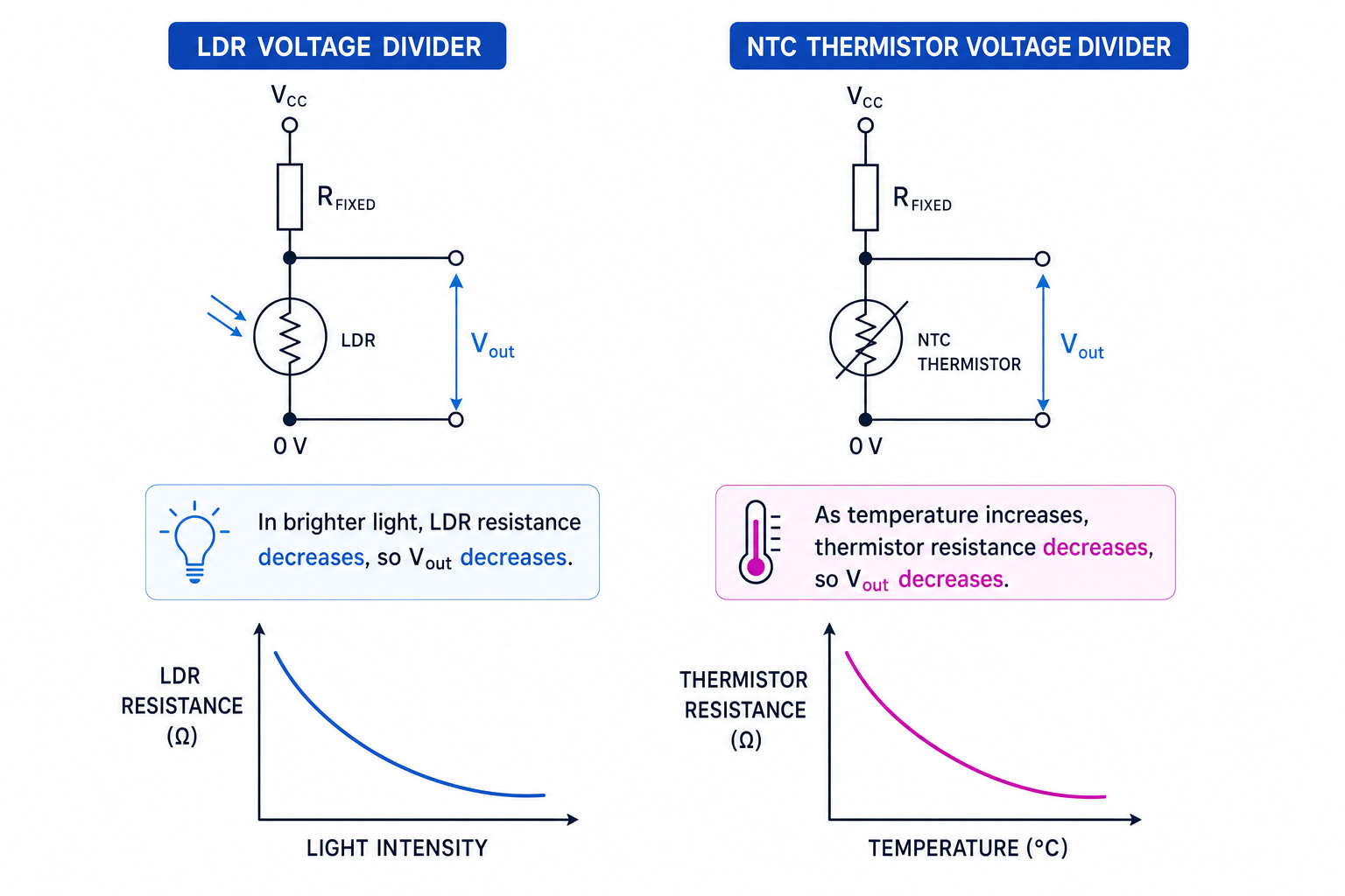
If the sensor is the lower resistor and VoutV_\text{out}Vout is measured across it:
Vout=VsRsensorRfixed+RsensorV_\text{out} = V_s\frac{R_\text{sensor}}{R_\text{fixed} + R_\text{sensor}}Vout=VsRfixed+RsensorRsensorSo if the sensor resistance decreases, VoutV_\text{out}Vout decreases.
If the sensor is the top resistor and VoutV_\text{out}Vout is measured across a fixed lower resistor, a decrease in sensor resistance makes VoutV_\text{out}Vout increase instead.
Example
Finding how light changes the output
An LDR is used as the lower resistor in a potential divider with a 6.0 V supply. The fixed top resistor is 4.7 kΩ. The LDR resistance is 20 kΩ in dim light and 1.0 kΩ in bright light. Find VoutV_\text{out}Vout in each case.
-
Since the output is across the LDR, put the LDR resistance in the numerator:
Vout=VsRLDRRfixed+RLDRV_\text{out} = V_s\frac{R_\text{LDR}}{R_\text{fixed} + R_\text{LDR}}Vout=VsRfixed+RLDRRLDR -
Calculate the dim-light output:
Vout=6.0 V×204.7+20=4.9 VV_\text{out} = 6.0\ \text{V} \times \frac{20}{4.7 + 20} = 4.9\ \text{V}Vout=6.0 V×4.7+2020=4.9 V -
Calculate the bright-light output:
Vout=6.0 V×1.04.7+1.0=1.1 VV_\text{out} = 6.0\ \text{V} \times \frac{1.0}{4.7 + 1.0} = 1.1\ \text{V}Vout=6.0 V×4.7+1.01.0=1.1 V -
Compare the outputs: as light intensity increases, the LDR resistance decreases, so the output voltage decreases.
Common Mistake
Assuming sensor output always increases
For an LDR or NTC thermistor, the resistance decreases when the input increases. Whether VoutV_\text{out}Vout increases or decreases depends on whether the sensor is above or below the output point.
Designing and calibrating sensor circuits
Definition
Sensitivity
Sensitivity means how much the output voltage changes for a given change in the physical quantity being measured.
A potential divider is most sensitive when the fixed resistor is similar in size to the sensor resistance in the range you care about. If one resistance is much larger than the other, the output may be stuck close to zero or close to the supply voltage.
In practical work, you might vary light intensity or temperature and measure VoutV_\text{out}Vout with a voltmeter or data logger. A calibration graph of output voltage against the measured quantity lets you convert voltage readings into physical measurements.
Example
Choosing a fixed resistor
An NTC thermistor is used as the lower resistor in a potential divider with a 5.0 V supply. At the required switching temperature, its resistance is 3.0 kΩ. You want VoutV_\text{out}Vout to be 2.0 V at this temperature. Find the fixed resistor needed above the thermistor.
-
Start with the divider equation:
Vout=VsRTRfixed+RTV_\text{out} = V_s\frac{R_T}{R_\text{fixed} + R_T}Vout=VsRfixed+RTRT -
Rearrange for the fixed resistor:
Rfixed=RT(VsVout−1)R_\text{fixed} = R_T\left(\frac{V_s}{V_\text{out}} - 1\right)Rfixed=RT(VoutVs−1) -
Substitute the values:
Rfixed=3.0 kΩ(5.02.0−1)R_\text{fixed} = 3.0\ \text{k}\Omega \left(\frac{5.0}{2.0} - 1\right)Rfixed=3.0 kΩ(2.05.0−1) -
Calculate the result:
Rfixed=4.5 kΩR_\text{fixed} = 4.5\ \text{k}\OmegaRfixed=4.5 kΩ
A nearby standard value such as 4.7 kΩ would usually be chosen.
Loading the potential divider
The simple divider equation assumes that the output is measured by a device with very high resistance, so almost no current leaves the divider at the output point.
A load is any component connected to the output terminals that draws current. If the load has a low resistance, it is effectively in parallel with the output resistor, changing the circuit.
Common Mistake
The divider formula assumes no significant load
If a load is connected across the output, first combine the load resistance in parallel with the output resistor. Then use the potential divider equation with this new effective resistance.
Example
Allowing for a load
A 5.0 V supply is connected across two 10 kΩ resistors, with VoutV_\text{out}Vout across the lower resistor. A 10 kΩ load is then connected across the output. Find the loaded output voltage.
-
Without the load, equal resistors would share the voltage equally, giving 2.5 V.
-
The load is in parallel with the lower 10 kΩ resistor. Two equal 10 kΩ resistors in parallel have an effective resistance of 5.0 kΩ.
-
Use the divider equation with the new lower resistance:
Vout=5.0 V×5.0 kΩ10 kΩ+5.0 kΩV_\text{out} = 5.0\ \text{V} \times \frac{5.0\ \text{k}\Omega}{10\ \text{k}\Omega + 5.0\ \text{k}\Omega}Vout=5.0 V×10 kΩ+5.0 kΩ5.0 kΩ -
Calculate the loaded output:
Vout=1.7 VV_\text{out} = 1.7\ \text{V}Vout=1.7 V
The load has pulled the output voltage down significantly.
Exam technique
In the exam
- Mark exactly where VoutV_\text{out}Vout is measured before choosing the resistor for the numerator.
- Keep resistance units consistent; kΩ can be used directly in ratios because the units cancel.
- For LDRs and NTC thermistors, decide whether the sensor resistance increases or decreases, then apply the divider equation.
- If a load is connected across the output, combine parallel resistances before calculating VoutV_\text{out}Vout.
Self review
Check yourself
- If VoutV_\text{out}Vout is measured across the lower resistor, what happens to VoutV_\text{out}Vout when that resistor increases?
- Why does an LDR potential divider not always give a higher output in brighter light?
- Why should a voltmeter used to measure VoutV_\text{out}Vout have a very high resistance?