Revision notes for Edexcel A Level Physics Lenses and optical images. Open the guide for explanations and worked examples. Written against the Edexcel A Level Physics (9PH0) specification, so the content matches what's examinable rather than general Physics background.
Lenses and optical images
What you'll learn
- How converging and diverging lenses bend light rays.
- How to draw ray diagrams for real and virtual images.
- How to use the thin lens equation and magnification equation.
- How focal length links to lens power and practical measurements.
Lenses start with refraction
A lens forms images by refraction: light changes direction when it passes between materials where it travels at different speeds, such as air and glass.
A curved lens surface makes different parts of the wavefront bend by different amounts, so rays can be brought together or spread apart.
Definition
Lens
A lens is a transparent optical component that changes the direction of light rays by refraction. In A-Level ray diagrams, we usually use the thin lens approximation, treating the lens as if all refraction happens at one vertical line through its centre.
Key lens terms
Before drawing images, you need a few labels.
Definition
Principal axis, optical centre and focus
- The principal axis is the straight line through the centre of the lens, perpendicular to the lens.
- The optical centre is the point at the centre of a thin lens; a ray through it is drawn as continuing undeviated.
- The principal focus, labelled FFF, is where rays parallel to the principal axis meet, or appear to come from.
- The focal length, fff, is the distance from the optical centre to the principal focus, measured in metres.
A converging lens is thicker in the middle than at the edges. It brings parallel rays together. A diverging lens is thinner in the middle than at the edges. It spreads parallel rays out.
Key Idea
Lens shape determines ray behaviour
A converging lens makes parallel rays meet at a focus. A diverging lens makes parallel rays spread out as if they came from a focus on the object side.
Real and virtual images
An image is formed when rays from the same point on an object meet, or seem to meet.
Definition
Real and virtual images
A real image is formed where light rays actually meet, so it can be projected onto a screen. A virtual image is formed where rays only appear to come from, so it cannot be projected onto a screen.
Real images formed by a single converging lens are usually inverted, meaning upside down. Virtual images are usually upright, meaning the same way up as the object.
Ray diagrams for a converging lens
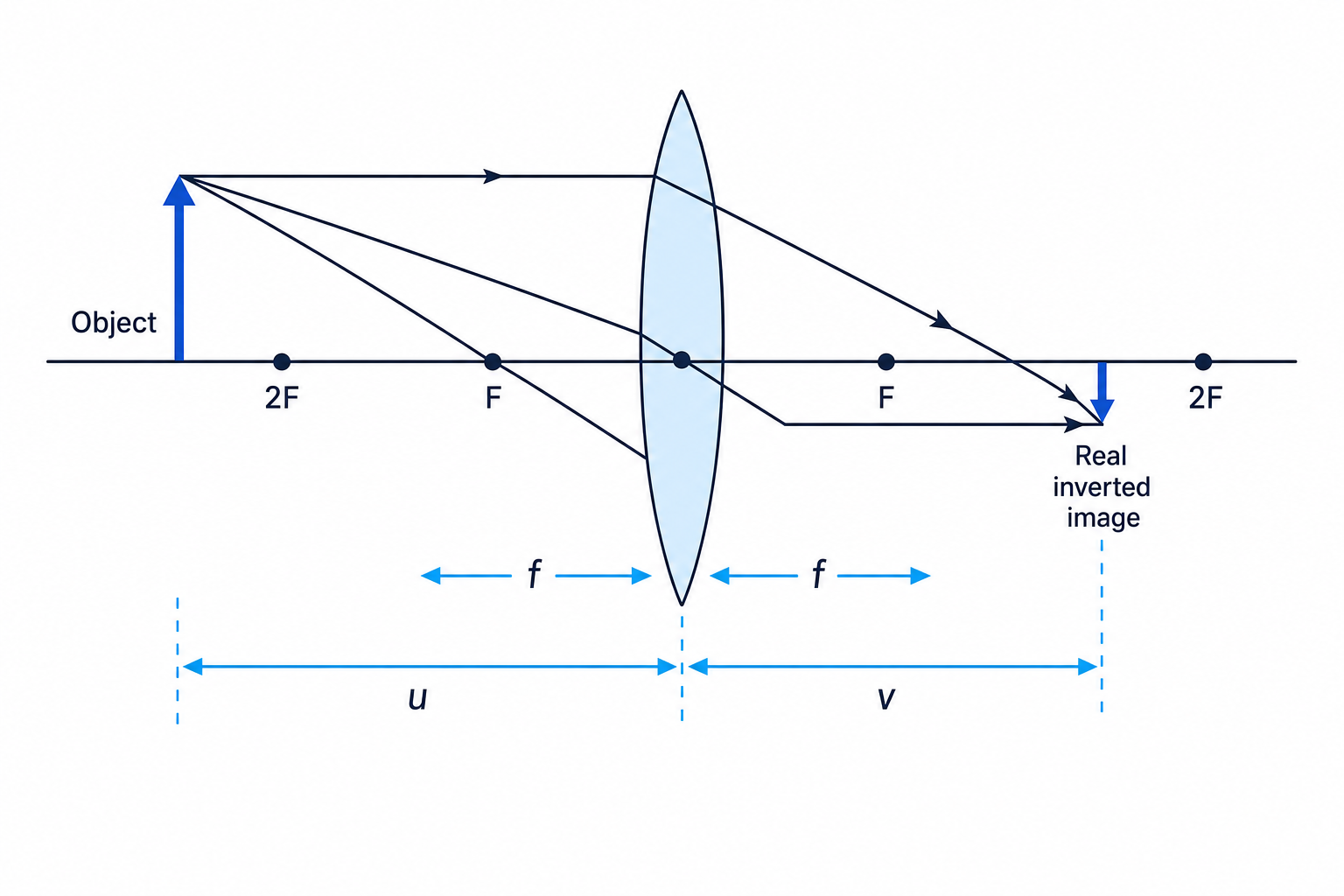
To locate an image, draw rays from the top of the object. You only need two correct rays, but a third ray is a useful check.
For a converging lens:
- A ray parallel to the principal axis refracts through the far focus.
- A ray through the optical centre continues straight.
- A ray through the near focus emerges parallel to the principal axis.
The diagram below shows a converging lens forming a real, inverted, smaller image when the object is placed beyond 2F2F2F.
Example
Predicting a real image
An object is placed 0.30 m from a converging lens of focal length 0.10 m. Predict the image type and position.
- Compare the object distance with the focal length: u=0.30 mu=0.30\ \text{m}u=0.30 m and 2f=0.20 m2f=0.20\ \text{m}2f=0.20 m, so the object is beyond 2F2F2F.
- For a converging lens with the object beyond 2F2F2F, the refracted rays meet on the other side of the lens between FFF and 2F2F2F.
- The image is therefore real, inverted and diminished.
Common Mistake
Forgetting the rays must come from one object point
Draw all principal rays from the same point, usually the top of the object. The image top is where those rays meet, not where random rays cross the axis.
Virtual images with lenses
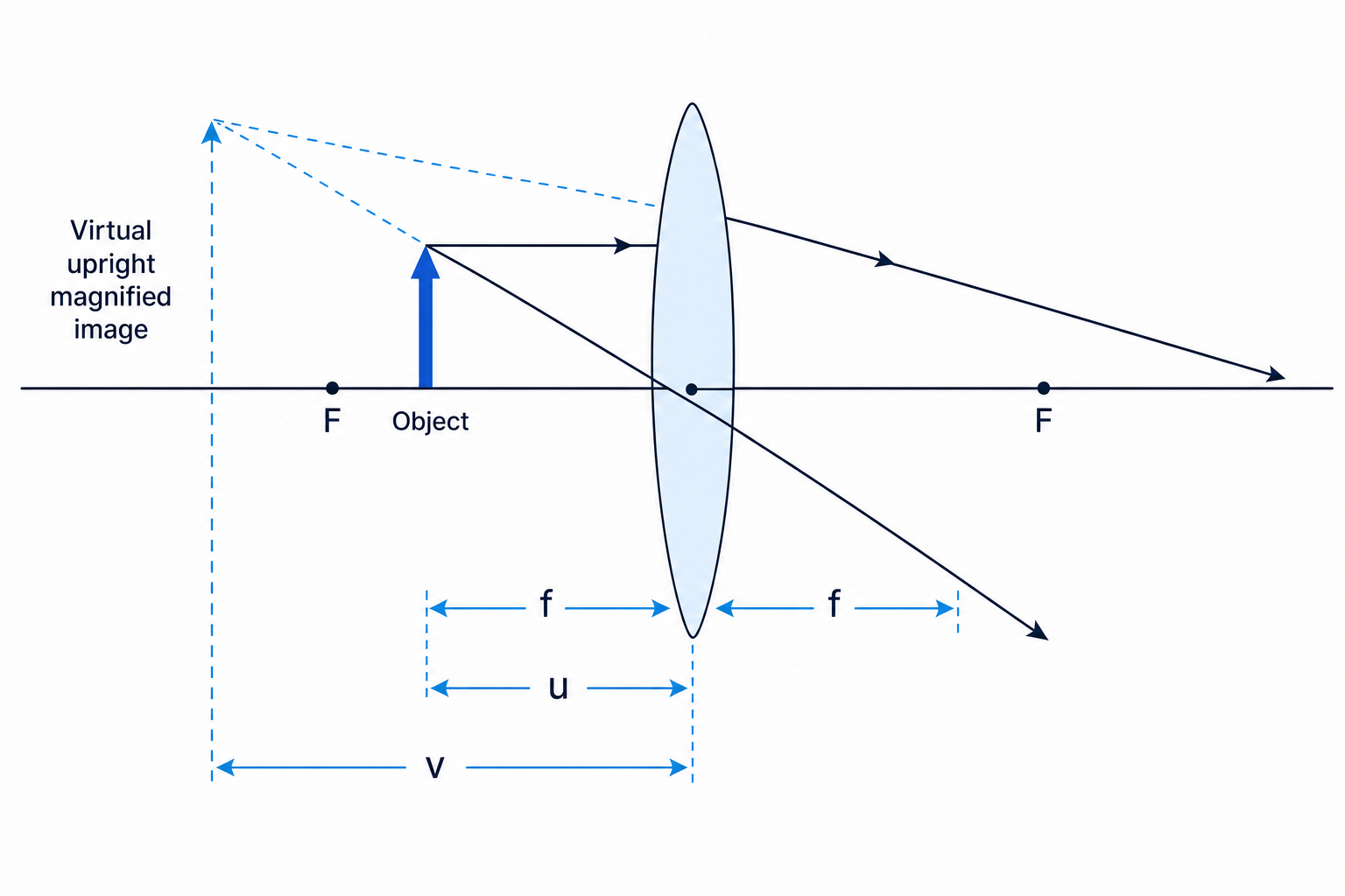
If an object is placed inside the focal length of a converging lens, the outgoing rays diverge. Your eye traces them backwards, so the image appears on the same side of the lens as the object. This is how a simple magnifying glass works.
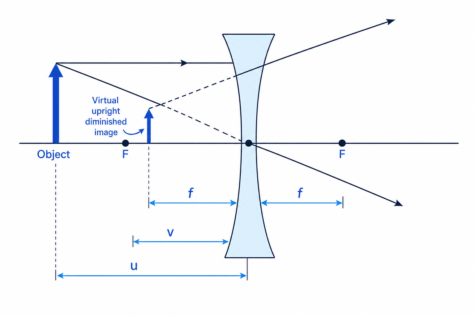
A diverging lens forms a virtual, upright, diminished image for a real object. The rays spread out after passing through the lens, and their backward extensions meet on the object side.
Tip
Dashed lines mean apparent rays
For a virtual image, draw the real refracted rays as solid lines, then extend them backwards with dashed lines. The dashed lines show where the rays appear to have come from.
The thin lens equation
For a thin lens, the object distance uuu, image distance vvv and focal length fff are related by:
1u+1v=1f\frac{1}{u}+\frac{1}{v}=\frac{1}{f}u1+v1=f1Use distances in metres. If you are using the common signed convention:
- f>0f>0f>0 for a converging lens.
- f<0f<0f<0 for a diverging lens.
- v>0v>0v>0 for a real image on the far side of the lens.
- v<0v<0v<0 for a virtual image on the same side as the object.
Common Mistake
Use one sign convention consistently
Some questions use only positive distances for real-image situations. If a question involves a virtual image or a diverging lens, be especially careful to follow the sign convention stated or implied by the question.
Magnification
The magnification, MMM, tells you how many times larger the image is than the object:
M=image heightobject height=vuM=\frac{\text{image height}}{\text{object height}}=\frac{v}{u}M=object heightimage height=uvFor simple A-Level calculations, this equation often uses the magnitudes of uuu and vvv. Magnification has no unit.
Example
Calculating image position and magnification
A 60 mm tall object is placed 0.300 m from a converging lens with focal length 0.100 m. Find the image distance and image height.
-
Use the lens equation and rearrange for vvv:
1v=1f−1u\frac{1}{v}=\frac{1}{f}-\frac{1}{u}v1=f1−u1 -
Substitute the distances in metres:
1v=10.100 m−10.300 m=10.0 m−1−3.33 m−1\frac{1}{v}=\frac{1}{0.100\ \text{m}}-\frac{1}{0.300\ \text{m}}=10.0\ \text{m}^{-1}-3.33\ \text{m}^{-1}v1=0.100 m1−0.300 m1=10.0 m−1−3.33 m−1 -
Invert the result:
v=16.67 m−1=0.150 mv=\frac{1}{6.67\ \text{m}^{-1}}=0.150\ \text{m}v=6.67 m−11=0.150 m -
Calculate magnification:
M=vu=0.150 m0.300 m=0.500M=\frac{v}{u}=\frac{0.150\ \text{m}}{0.300\ \text{m}}=0.500M=uv=0.300 m0.150 m=0.500 -
Find the image height:
image height=0.500×60 mm=30 mm\text{image height}=0.500\times 60\ \text{mm}=30\ \text{mm}image height=0.500×60 mm=30 mm
The image is real, inverted and half the height of the object.
Tip
Quick lens equation sanity check
For a converging lens, if the object is just outside the focus, the image distance should be very large. If the object is very far away, the image forms close to the focal plane.
Lens power
The power of a lens tells you how strongly it converges or diverges light.
P=1fP=\frac{1}{f}P=f1Here fff must be in metres. The unit of lens power is the dioptre, symbol D, equivalent to m−1\text{m}^{-1}m−1.
A converging lens has positive power. A diverging lens has negative power.
Example
Finding lens power
A converging lens has focal length 25.0 cm. Calculate its power.
-
Convert the focal length into metres: f=25.0 cm=0.250 mf=25.0\ \text{cm}=0.250\ \text{m}f=25.0 cm=0.250 m.
-
Substitute into P=1fP=\frac{1}{f}P=f1:
P=10.250 m=4.00 m−1P=\frac{1}{0.250\ \text{m}}=4.00\ \text{m}^{-1}P=0.250 m1=4.00 m−1 -
State the sign and unit: the lens power is plus 4.00 D.
Common Mistake
Using centimetres in lens power
Do not put focal length in centimetres when calculating P=1fP=\frac{1}{f}P=f1. A lens with focal length 25 cm has power 4 D, not 0.04 D.
Measuring focal length practically
For a converging lens, you can estimate fff by focusing a distant object, such as a window or lamp, onto a screen. If the object is very far away, uuu is very large, so 1u\frac{1}{u}u1 is close to zero and v≈fv\approx fv≈f.
For a more careful method, measure several pairs of uuu and vvv using an optical bench, lens holder and screen. Rearrange the lens equation:
1v=−1u+1f\frac{1}{v}=-\frac{1}{u}+\frac{1}{f}v1=−u1+f1A graph of 1v\frac{1}{v}v1 against 1u\frac{1}{u}u1 should have gradient close to minus 1 and y-intercept 1f\frac{1}{f}f1.
Tip
Practical accuracy
Measure distances from the optical centre of the lens, keep the lens and screen vertical, and repeat readings. The biggest uncertainty is often judging the sharpest image on the screen.
Exam technique
In the exam
- Start lens questions with a quick ray sketch, even if the question mainly asks for calculation.
- Convert all distances to metres before using the lens equation or lens power equation.
- Check your numerical answer against the ray diagram: real or virtual, upright or inverted, magnified or diminished.
Self review
Check yourself
- What type of image does a converging lens form when the object is between FFF and 2F2F2F?
- Why can a real image be formed on a screen, but a virtual image cannot?
- A lens has focal length 0.200 m. What is its power, and what sign would it have if it were diverging?