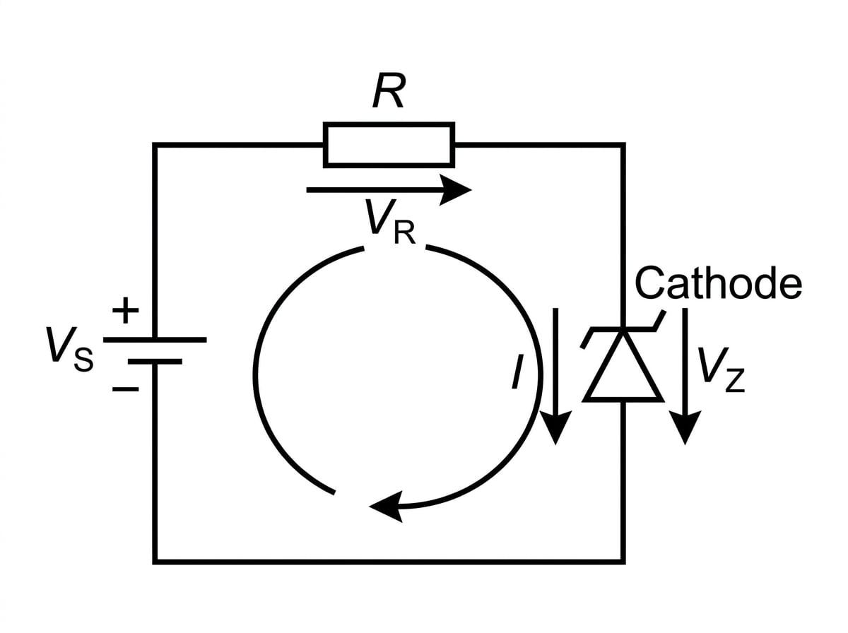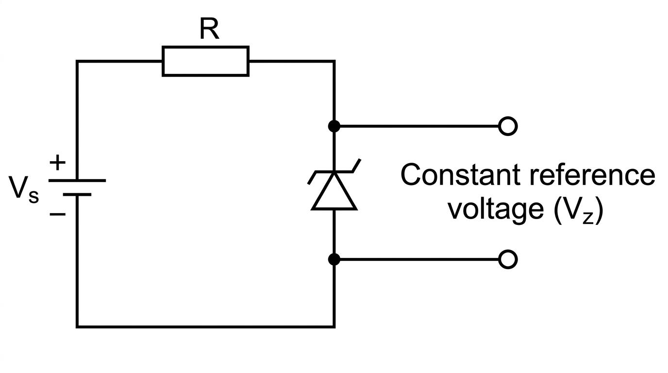
Here is how the circuit works:
- The supply voltage VSV_SVS is shared between the series resistor RRR and the Zener diode.
- The Zener diode "claims" its breakdown voltage, VZV_ZVZ.
- The rest of the voltage is dropped across the resistor. Therefore, the voltage across the resistor is exactly VR=VS−VZV_R = V_S - V_ZVR=VS−VZ.
- The resistor limits the total current flowing through the circuit, protecting the Zener diode.
Voltage distribution
In a Zener reference circuit, the sum of the voltages must equal the supply voltage.
VS=VR+VZ V_S = V_R + V_Z VS=VR+VZWhere VSV_SVS is the supply voltage, VRV_RVR is the voltage across the series resistor, and VZV_ZVZ is the Zener voltage.
Let's look at how AQA tests this with some calculations.
Calculating the required series resistor
A circuit is built to provide a stable 5.0 V5.0 \text{ V}5.0 V reference voltage from a 9.0 V9.0 \text{ V}9.0 V DC battery. The designer uses a Zener diode with a breakdown voltage of 5.0 V5.0 \text{ V}5.0 V. The manufacturer specifies that the typical minimum operating current to keep the diode in breakdown is 2.0 mA2.0 \text{ mA}2.0 mA.
Calculate the maximum value of the series resistor RRR that guarantees the Zener diode receives its minimum operating current.
- Find the voltage across the series resistor. The Zener diode locks the voltage across itself at 5.0 V5.0 \text{ V}5.0 V. The remaining voltage from the 9.0 V9.0 \text{ V}9.0 V supply is dropped across the resistor:
- State the condition for maximum resistance. From Ohm's law (R=VIR = \frac{V}{I}R=IV), for a fixed voltage, the resistance is maximum when the current is at its minimum allowed value. The minimum current is given as 2.0 mA2.0 \text{ mA}2.0 mA.
- Calculate the resistance. Substitute the values into Ohm's law (remembering to convert milliamps to amps):
So, a maximum resistance of 2000 Ω2000 \ \Omega2000 Ω (or 2 kΩ2 \text{ k}\Omega2 kΩ) can be used.
Spec limits
The AQA specification states: "Use as a stabiliser is not required." This means you will only be asked to evaluate the circuit as a simple provider of a reference voltage (no external load, or very simple loads), not complex calculations involving a varying load resistor drawing different amounts of current. Focus purely on the relationship between VSV_SVS, VZV_ZVZ, VRV_RVR, and the current in that single loop!
Calculating power dissipation
A 12 V12 \text{ V}12 V power supply is connected in series with a 150 Ω150 \ \Omega150 Ω resistor and a Zener diode. The Zener diode has a breakdown voltage of 7.5 V7.5 \text{ V}7.5 V. Calculate the power dissipated by the Zener diode.
- Calculate the voltage across the series resistor.
- Calculate the current flowing through the circuit. Use Ohm's law on the resistor:
- Calculate the power dissipated by the Zener diode. We know the current through the Zener (0.030 A0.030 \text{ A}0.030 A) and the voltage across it (7.5 V7.5 \text{ V}7.5 V). Use the electrical power equation:
(which is 225 mW225 \text{ mW}225 mW).
In the exam
- Check the bias: Always check the polarity of the diode in the diagram. To act as a reference voltage, a Zener diode must be reverse-biased (cathode connected to the positive terminal).
- Find the resistor voltage first: The single most common first step in any Zener diode math problem is finding the voltage dropped across the series resistor using VR=VS−VZV_R = V_S - V_ZVR=VS−VZ.
- Watch your prefixes: Currents in Zener diodes are often given in mA\text{mA}mA (milliamps). Remember to multiply by 10−310^{-3}10−3 before using them in Ohm's law or power equations.
- Know the curve: If asked to sketch the I-V curve, don't forget the forward bias section! It behaves just like a normal diode for positive voltages, turning on at around 0.7 V0.7 \text{ V}0.7 V.
Check yourself
- Can you describe the difference between how a standard diode and a Zener diode behave in reverse bias?
- Why is it necessary to connect a resistor in series with a Zener diode when creating a reference voltage circuit?
- If a 10 V10 \text{ V}10 V supply is connected to a 3.3 V3.3 \text{ V}3.3 V Zener diode and a 100 Ω100 \ \Omega100 Ω series resistor, what is the voltage across the resistor?
- What does the "typical minimum operating current" represent on the I-V characteristic curve?