The operation of a transformer (A-level only)
What you'll learn
- How transformers use electromagnetic induction to step alternating voltages up or down.
- How to use the transformer turns ratio equation and calculate transformer efficiency.
- Why real transformers aren't completely efficient (including the production of eddy currents).
- Why the National Grid relies on high-voltage transformers to minimise power loss over long distances.
How a transformer works
A transformer is a device that changes the amplitude of an alternating voltage. If you've ever charged a laptop from the mains or looked at the massive pylons connecting the National Grid, you are relying on transformers.
Transformers operate entirely on the principle of Faraday's Law of electromagnetic induction. A basic transformer consists of two coils of wire—the primary coil and the secondary coil—wound around a single continuous ring of magnetic material, usually a soft iron core.
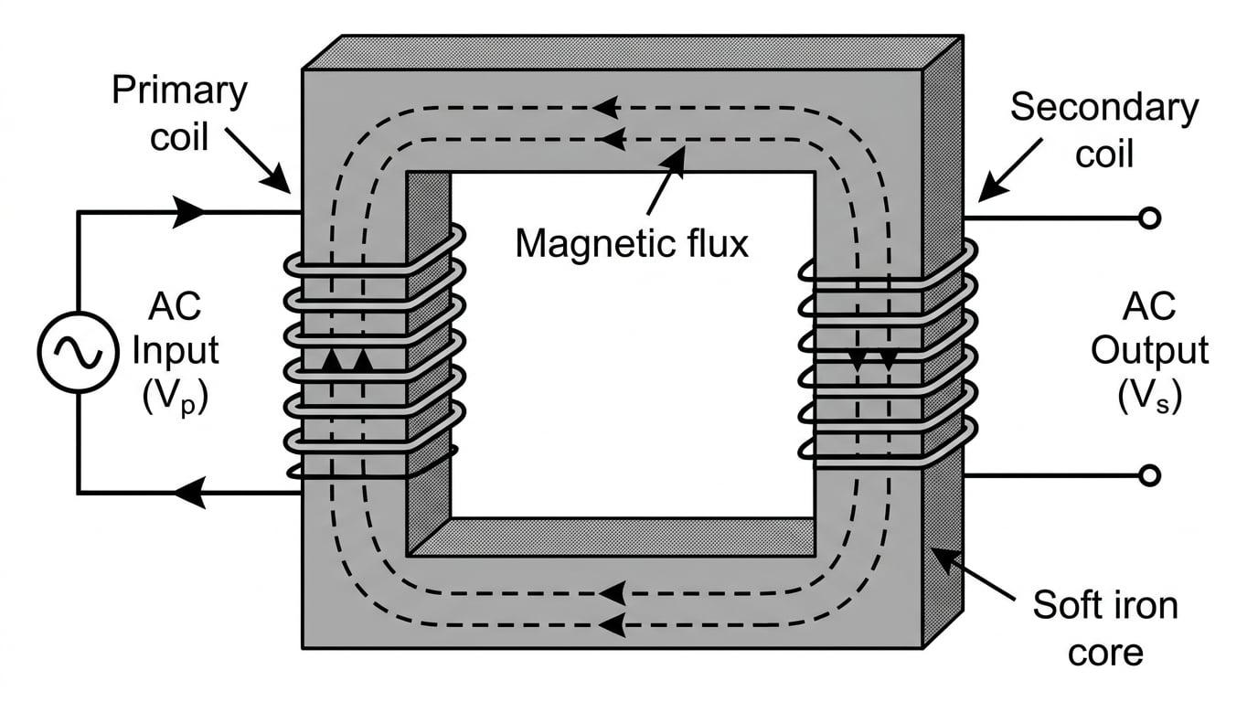
Here is the step-by-step physical process of how they work:
- An alternating voltage is applied across the primary coil.
- This drives an alternating current (AC) through the primary coil.
- The alternating current creates a continuously changing magnetic field around the primary coil.
- The soft iron core provides a highly permeable path, channeling this changing magnetic flux through to the secondary coil.
- Because the secondary coil is sitting in a changing magnetic flux, an alternating electromotive force (emf) is induced across it (Faraday's Law).
Why direct current (DC) fails
If you apply a steady direct current to the primary coil, a constant magnetic field is produced. Because the magnetic flux is constant (not changing), no emf will be induced in the secondary coil. Transformers only work with alternating current!
The Transformer Equation
The size of the voltage induced in the secondary coil depends entirely on the ratio of the number of turns of wire on each coil.
If we assume the transformer is "ideal" (meaning all the magnetic flux from the primary coil passes through the secondary coil with no losses), the relationship is given by the transformer equation:
NsNp=VsVp\frac{N_s}{N_p} = \frac{V_s}{V_p}NpNs=VpVsWhere:
- NsN_sNs is the number of turns on the secondary coil.
- NpN_pNp is the number of turns on the primary coil.
- VsV_sVs is the voltage across the secondary coil (in volts, V).
- VpV_pVp is the voltage across the primary coil (in volts, V).
Step-up and Step-down transformers
- Step-up transformer: Has more turns on the secondary coil (Ns>NpN_s > N_pNs>Np). It increases the alternating voltage (Vs>VpV_s > V_pVs>Vp).
- Step-down transformer: Has fewer turns on the secondary coil (Ns<NpN_s < N_pNs<Np). It decreases the alternating voltage (Vs<VpV_s < V_pVs<Vp).
Calculating secondary voltage
A step-up transformer has 400 turns on its primary coil and 2000 turns on its secondary coil. It is connected to a 230 V230 \text{ V}230 V mains supply. Calculate the output voltage of the transformer.
- Identify the given values: Np=400N_p = 400Np=400, Ns=2000N_s = 2000Ns=2000, and Vp=230 VV_p = 230 \text{ V}Vp=230 V.
- Rearrange the transformer equation to make VsV_sVs the subject: Vs=Vp×NsNpV_s = V_p \times \frac{N_s}{N_p}Vs=Vp×NpNs
- Substitute the values into the equation: Vs=230×2000400V_s = 230 \times \frac{2000}{400}Vs=230×4002000
- Calculate the final answer: Vs=230×5=1150 VV_s = 230 \times 5 = 1150 \text{ V}Vs=230×5=1150 V
Transformer Efficiency
An ideal transformer is 100% efficient, meaning the electrical power entering the primary coil is completely transferred to the secondary coil.
Remembering that electrical power P=IVP = IVP=IV, for an ideal transformer:
IpVp=IsVsI_p V_p = I_s V_sIpVp=IsVsVoltage goes up, current goes down
If a step-up transformer increases the voltage by a factor of 10, it must simultaneously decrease the current by a factor of 10 to conserve energy. You cannot get more power out of a transformer than you put in!
In reality, transformers are very efficient (often above 98%), but never perfectly 100%. We calculate the efficiency using the ratio of useful power output to total power input:
Efficiency=IsVsIpVp\text{Efficiency} = \frac{I_s V_s}{I_p V_p}Efficiency=IpVpIsVs(Note: To express this as a percentage, simply multiply the result by 100).
Calculating efficiency
A step-down transformer is connected to a 3300 V3300 \text{ V}3300 V supply and draws a primary current of 2.5 A2.5 \text{ A}2.5 A. The secondary coil supplies a current of 24 A24 \text{ A}24 A at a voltage of 320 V320 \text{ V}320 V. Calculate the efficiency of the transformer.
- Calculate the input power (Pin=IpVpP_{\text{in}} = I_p V_pPin=IpVp): Pin=2.5×3300=8250 WP_{\text{in}} = 2.5 \times 3300 = 8250 \text{ W}Pin=2.5×3300=8250 W
- Calculate the output power (Pout=IsVsP_{\text{out}} = I_s V_sPout=IsVs): Pout=24×320=7680 WP_{\text{out}} = 24 \times 320 = 7680 \text{ W}Pout=24×320=7680 W
- Use the efficiency formula: Efficiency=76808250\text{Efficiency} = \frac{7680}{8250}Efficiency=82507680
- Convert to a percentage: Efficiency=0.9309...≈93.1%\text{Efficiency} = 0.9309... \approx 93.1\%Efficiency=0.9309...≈93.1%
Causes of inefficiencies in a transformer
If power is lost, where does it go? Almost all lost energy in a transformer is dissipated as heat. You need to know the four main causes of inefficiency and, crucially, how engineers design transformers to minimise them.
1. Copper losses (Joule heating)
The copper wires forming the primary and secondary coils have resistance. As alternating current flows through them, they heat up, dissipating power equal to I2RI^2 RI2R. How it is reduced: Use thick copper wire with a large cross-sectional area to keep the resistance RRR as low as possible.
2. Eddy currents
The soft iron core is a metal, meaning it is an electrical conductor. Because it is sitting in a continuously changing magnetic field, Faraday's Law states that emfs will be induced inside the core itself.
Eddy currents
Small, circulating loops of induced alternating current entirely within the metal core of the transformer. They cause the core to heat up due to the metal's electrical resistance.
How it is reduced: The core is laminated. Instead of a solid block of iron, the core is built from many thin layers (laminae) of iron separated by thin layers of insulating material. This greatly increases the electrical resistance of the core in the direction the eddy currents want to flow, reducing their size and minimising the I2RI^2 RI2R heat loss.
3. Hysteresis losses
The alternating current causes the magnetic field in the core to constantly flip back and forth (50 times a second for UK mains). Energy is required to constantly re-align the magnetic domains in the iron core. How it is reduced: The core is made of a "magnetically soft" material, like soft iron, which is easy to magnetise and demagnetise.
4. Flux leakage
Not all the magnetic flux generated by the primary coil manages to travel through the core to cut the secondary coil. How it is reduced: The primary and secondary coils are often wound as close to each other as possible, sometimes physically layered on top of one another around the same part of the core.
High-Voltage Power Transmission
The ultimate application of transformers is the National Grid. Power stations generate electricity, which then needs to be transmitted over hundreds of kilometres to towns and cities.
Transmission cables have an electrical resistance, RRR. When a current III flows through them, they act like giant heaters, wasting power into the atmosphere. The power lost as heat in the transmission lines is given by:
Ploss=I2RP_{\text{loss}} = I^2 RPloss=I2RBecause the current III is squared in this equation, even a small reduction in current leads to a massive reduction in wasted power.
To transmit a specific amount of power (P=IVP = IVP=IV), we can either use a high current and a low voltage, or a low current and a high voltage. By using a step-up transformer at the power station, we drastically increase the transmission voltage VVV, which proportionally shrinks the current III.
Using the wrong power equation
When calculating power lost in the cables, always use Ploss=I2RP_{\text{loss}} = I^2 RPloss=I2R. Do not use Ploss=V2RP_{\text{loss}} = \frac{V^2}{R}Ploss=RV2. The VVV in that formula refers to the potential difference across the ends of the cable, not the transmission voltage relative to the ground. Using it will give you the wrong answer and lose you marks!
Calculating power loss in transmission
A power station generates 120 kW120 \text{ kW}120 kW of electrical power. This is transmitted through cables with a total resistance of 4.0 \Omega4.0 \text{ \Omega}4.0 \Omega. Calculate the power lost as heat in the cables if the electricity is transmitted at: (a) 2000 V2000 \text{ V}2000 V (b) 40,000 V40,000 \text{ V}40,000 V
Part (a) - Transmitting at 2000 V2000 \text{ V}2000 V:
- Calculate the current in the cables using P=IVP = IVP=IV: I=PV=120,0002000=60 AI = \frac{P}{V} = \frac{120,000}{2000} = 60 \text{ A}I=VP=2000120,000=60 A
- Calculate the power lost using I2RI^2 RI2R: Ploss=602×4.0=3600×4.0=14,400 W (or 14.4 kW)P_{\text{loss}} = 60^2 \times 4.0 = 3600 \times 4.0 = 14,400 \text{ W} \text{ (or } 14.4 \text{ kW)}Ploss=602×4.0=3600×4.0=14,400 W (or 14.4 kW)
Part (b) - Transmitting at 40,000 V40,000 \text{ V}40,000 V:
- Calculate the new current: I=PV=120,00040,000=3.0 AI = \frac{P}{V} = \frac{120,000}{40,000} = 3.0 \text{ A}I=VP=40,000120,000=3.0 A
- Calculate the new power lost: Ploss=3.02×4.0=9×4.0=36 WP_{\text{loss}} = 3.0^2 \times 4.0 = 9 \times 4.0 = 36 \text{ W}Ploss=3.02×4.0=9×4.0=36 W
Notice the enormous difference: stepping the voltage up by a factor of 20 reduced the current by a factor of 20, which reduced the power loss by a factor of 20220^2202 (400 times less power wasted).
In the exam
- Be rigorous with your terms: If a question asks why laminated cores are used, clearly state that they increase electrical resistance, which reduces the size of the eddy currents, thereby reducing I2RI^2 RI2R heat loss in the core.
- Watch your prefixes: Voltages in power transmission are often given in kV\text{kV}kV and power in MW\text{MW}MW. Always convert these to V\text{V}V and W\text{W}W before using P=IVP = IVP=IV or P=I2RP = I^2 RP=I2R.
- Remember the sequence: Step-up transformer at the power station (high VVV, low III for transmission) →\rightarrow→ Step-down transformers near towns (to drop VVV back to safe levels for homes, like 230 V230 \text{ V}230 V).
Check yourself
- Can you explain why a transformer will not work if connected to a DC battery?
- Can you list the four main causes of energy loss in a transformer and state how each is minimised?
- If a transformer is 100% efficient and steps up the voltage by a factor of 5, what happens to the current?
- Why does doubling the transmission voltage of the National Grid cut the power lost in the cables by a quarter?