LC resonance filters (A-level only)
If you have ever tuned an analogue radio to your favourite station, you have used a resonance filter! In electronic circuits, we often need to isolate a single specific frequency from a chaotic mix of signals.
What you'll learn in this topic:
- How connecting an inductor and a capacitor in parallel creates an oscillating circuit.
- How to calculate the resonant frequency of this circuit.
- The beautiful physics analogy between an LC circuit and a mechanical mass-spring system.
- How to interpret an energy response curve and calculate the "quality" (QQQ factor) of the filter.
The parallel LC circuit
To create an electrical filter, we use two components you have already met: an inductor (a coil of wire, symbol LLL, measured in henrys) and a capacitor (two parallel plates, symbol CCC, measured in farads).
For AQA A-Level Physics, you only need to worry about the parallel arrangement of these two components.
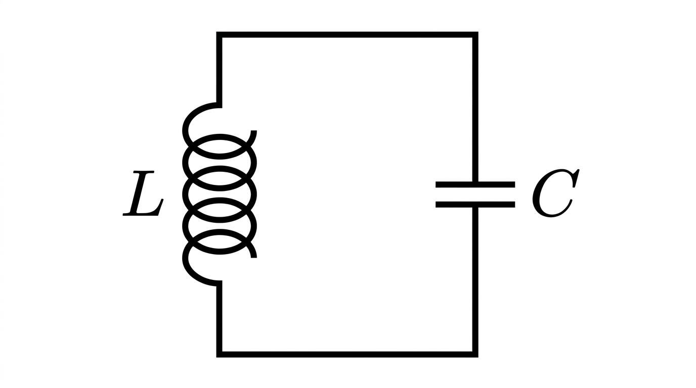
When a charged capacitor is connected across an inductor, it begins to discharge. The current flows through the inductor, generating a magnetic field. As the capacitor runs out of charge, the inductor's magnetic field collapses, keeping the current flowing and driving positive charge onto the opposite plate of the capacitor. The capacitor then discharges back the other way, and the cycle repeats.
This back-and-forth sloshing of energy creates an alternating electrical current. Just like a pendulum, this circuit has a natural frequency at which it "wants" to oscillate.
Resonant Frequency
The resonant frequency (f0f_0f0) is the natural frequency at which an LC circuit oscillates, where the exchange of energy between the capacitor and inductor is perfectly synchronised.
At this specific frequency, the parallel LC circuit acts as a highly effective filter, blocking or selecting that exact frequency while ignoring others.
Calculating resonant frequency
The formula for the resonant frequency of an LC circuit depends entirely on the size of the inductor and the capacitor.
f0=12πLC f_0 = \frac{1}{2\pi\sqrt{LC}} f0=2πLC1Where:
- f0f_0f0 is the resonant frequency in hertz (Hz)
- LLL is the inductance in henrys (H)
- CCC is the capacitance in farads (F)
Watch your units!
Inductors and capacitors in real circuits usually have very small values. You will almost always need to convert from milli (mH), micro (μ\muμF), nano (nF), or pico (pF) back into standard SI units before putting numbers into this formula.
Worked Example: Finding the required capacitance
A radio engineer is designing a parallel LC filter to isolate a radio signal with a frequency of 200 kHz200 \text{ kHz}200 kHz. They have chosen an inductor with an inductance of 4.0 mH4.0 \text{ mH}4.0 mH. Calculate the required capacitance of the capacitor.
-
Extract the data and convert to SI units: f0=200 kHz=200×103 Hzf_0 = 200 \text{ kHz} = 200 \times 10^3 \text{ Hz}f0=200 kHz=200×103 Hz L=4.0 mH=4.0×10⁻³ HL = 4.0 \text{ mH} = 4.0 \times 10^{-3} \text{ H}L=4.0 mH=4.0×10⁻³ H
-
State the formula:
- Rearrange the formula to make CCC the subject: Square both sides first to remove the square root:
Multiply by CCC and divide by f02f_0^2f02:
C=14π2f02L C = \frac{1}{4\pi^2 f_0^2 L} C=4π2f02L1- Substitute the values and calculate:
- State the final answer with a suitable prefix: The required capacitance is 158 pF158 \text{ pF}158 pF.
The mass-spring analogy
One of the most elegant concepts in physics is how completely different systems can obey exactly the same underlying mathematics. The electrical oscillations in an LC circuit are mathematically identical to the mechanical oscillations of a mass bouncing on a spring.
AQA expects you to know exactly which electrical component corresponds to which mechanical component.
- The Inductor acts like the Mass. Mass provides inertia, resisting changes in velocity. An inductor provides electrical inertia, resisting changes in current.
- The Capacitor acts like the Spring. A spring stores elastic potential energy when you stretch or compress it. A capacitor stores electrical energy when you push charge onto its plates.
Energy swapping
In a mass-spring system, energy constantly swaps between Elastic Potential Energy (in the spring) and Kinetic Energy (in the mass).
In an LC circuit, energy constantly swaps between Electrical Energy (stored in the capacitor's electric field) and Magnetic Energy (stored in the inductor's magnetic field).
If we take the mechanical formula for the time period of a mass-spring system (T=2πmkT = 2\pi\sqrt{\frac{m}{k}}T=2πkm) and swap mass (mmm) for inductance (LLL), and the spring stiffness factor (1/k1/k1/k) for capacitance (CCC), we end up with T=2πLCT = 2\pi\sqrt{LC}T=2πLC. Since frequency is 1/T1/T1/T, this perfectly matches our f0f_0f0 formula!
The energy response curve
If we feed a range of different input frequencies into our LC filter, it won't respond to all of them equally. The filter's response is maximum exactly at the resonant frequency, f0f_0f0, and drops off for frequencies that are higher or lower.
We visualise this using an energy response curve. (Note: AQA only requires you to know the response curve for energy/voltage, not for current).
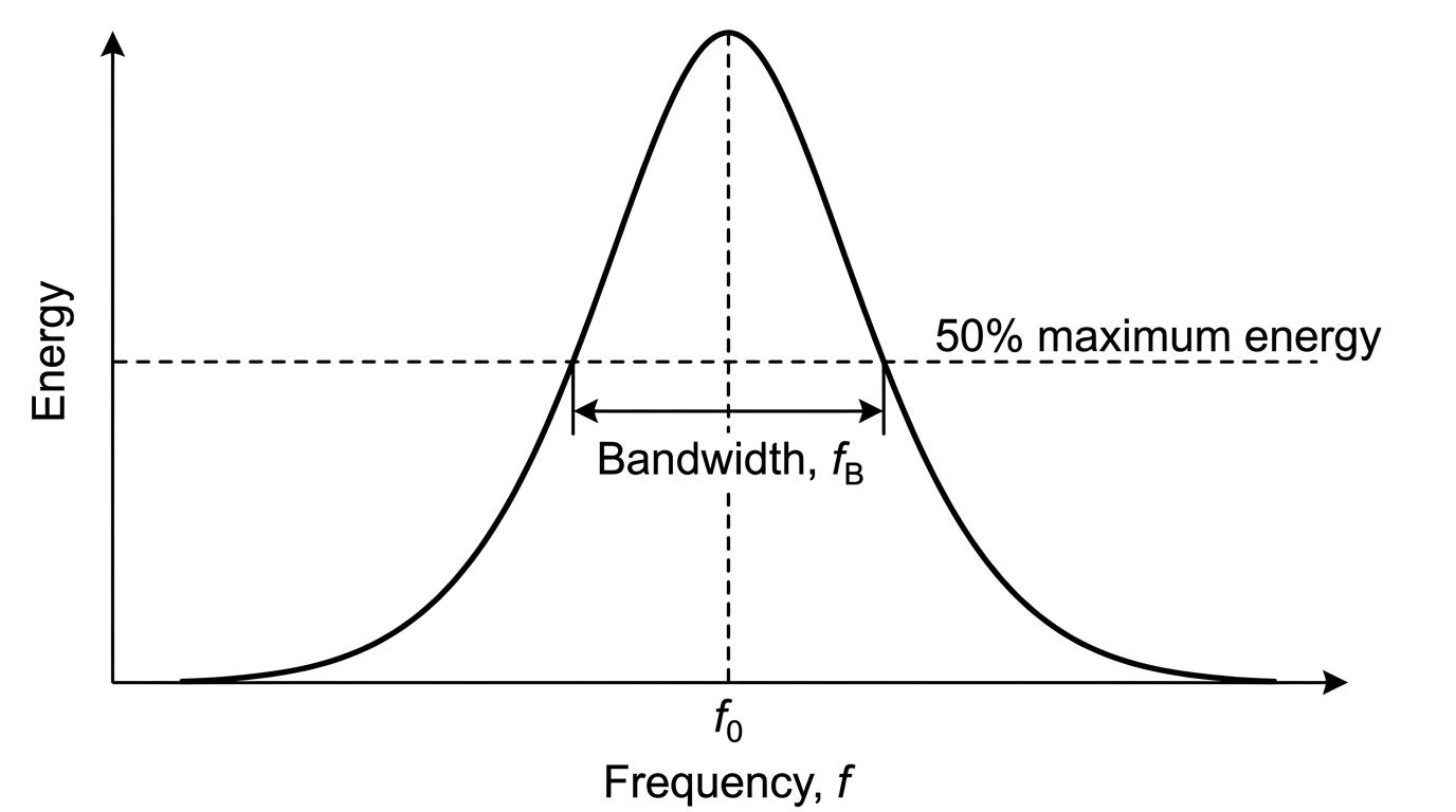
Notice the bell shape of the curve. The peak occurs at f0f_0f0. However, real circuits contain resistance (from the wires), which means some energy is lost as heat. This resistance dampens the oscillation, making the peak slightly wider rather than an infinitely thin spike.
To measure exactly how wide or "sharp" this peak is, we use a measurement called bandwidth.
Bandwidth
The bandwidth (fBf_BfB) of an LC filter is the difference between the two frequencies at which the energy falls to exactly 50% of its maximum value.
Voltage vs Energy
Be careful! The bandwidth is strictly measured at the 50% energy points. Because energy is proportional to voltage squared (E∝V2E \propto V^2E∝V2), the 50% energy point actually corresponds to a voltage of about 71% of maximum (specifically, Vmax/2V_{\text{max}} / \sqrt{2}Vmax/2). If an exam question asks about energy, look for the halfway mark on the y-axis.
The Q factor
When designing a filter to isolate a specific radio station, we want the peak to be as sharp and narrow as possible so that we don't accidentally tune into neighbouring stations at the same time.
We measure the quality of this sharpness using the QQQ factor (Quality factor).
Q=f0fB Q = \frac{f_0}{f_B} Q=fBf0Where:
- QQQ is the dimensionless quality factor
- f0f_0f0 is the resonant frequency (Hz)
- fBf_BfB is the bandwidth at the 50% energy points (Hz)
A high QQQ factor means the filter has a very narrow bandwidth relative to its resonant frequency—it is highly selective. A low QQQ factor means the peak is broad and "mushy".
Worked Example: Calculating Q factor from a graph
An LC filter has its maximum response energy at a frequency of 800 Hz800 \text{ Hz}800 Hz. By reading an energy response graph, a student determines that the energy drops to 50% of its maximum value at 785 Hz785 \text{ Hz}785 Hz and at 815 Hz815 \text{ Hz}815 Hz. Calculate the QQQ factor of this filter.
-
Identify the resonant frequency: The peak is at f0=800 Hzf_0 = 800 \text{ Hz}f0=800 Hz.
-
Calculate the bandwidth (fBf_BfB): The bandwidth is the difference between the upper and lower 50% energy frequencies.
- State the Q factor formula:
- Substitute the values and calculate:
- State the final answer: The QQQ factor is 26.726.726.7 (to 3 s.f.). Notice it has no units because it is a ratio of two frequencies.
In the exam
- Watch out for squaring: When rearranging f0=12πLCf_0 = \frac{1}{2\pi\sqrt{LC}}f0=2πLC1, the most common mistake is forgetting to square the 2π2\pi2π into 4π24\pi^24π2. Always write out the intermediate squared step to avoid dropping marks.
- Know your analogy pairs: Expect 1-mark multiple choice questions testing the mechanical analogy. Remember: Inductor = Mass (inertia), Capacitor = Spring (energy storage).
- Read graphs carefully: If you are given a response curve and asked for the QQQ factor, visually draw a horizontal line at half the maximum y-axis value, then drop down to read the two x-axis values to find fBf_BfB.
Check yourself
- What happens to the resonant frequency of a circuit if you quadruple the size of the capacitor?
- In the mass-spring analogy, what type of mechanical energy corresponds to the magnetic energy stored in the inductor?
- How is the bandwidth fBf_BfB formally defined for an LC resonance filter in the AQA specification?