summing amplifier configuration (A-level only)
What you'll learn:
- How to combine multiple input voltages into a single output using a summing amplifier.
- How to amplify the difference between two signals using a difference amplifier.
- How to use the standard formulas for both configurations (without needing to derive them!).
You have already seen how an operational amplifier can be used to multiply a single signal by a constant factor (the inverting and non-inverting configurations). But what if we want to combine multiple signals together, or subtract one signal from another?
In this section, we will look at two very useful op-amp circuits: the summing amplifier and the difference amplifier.
The Summing Amplifier
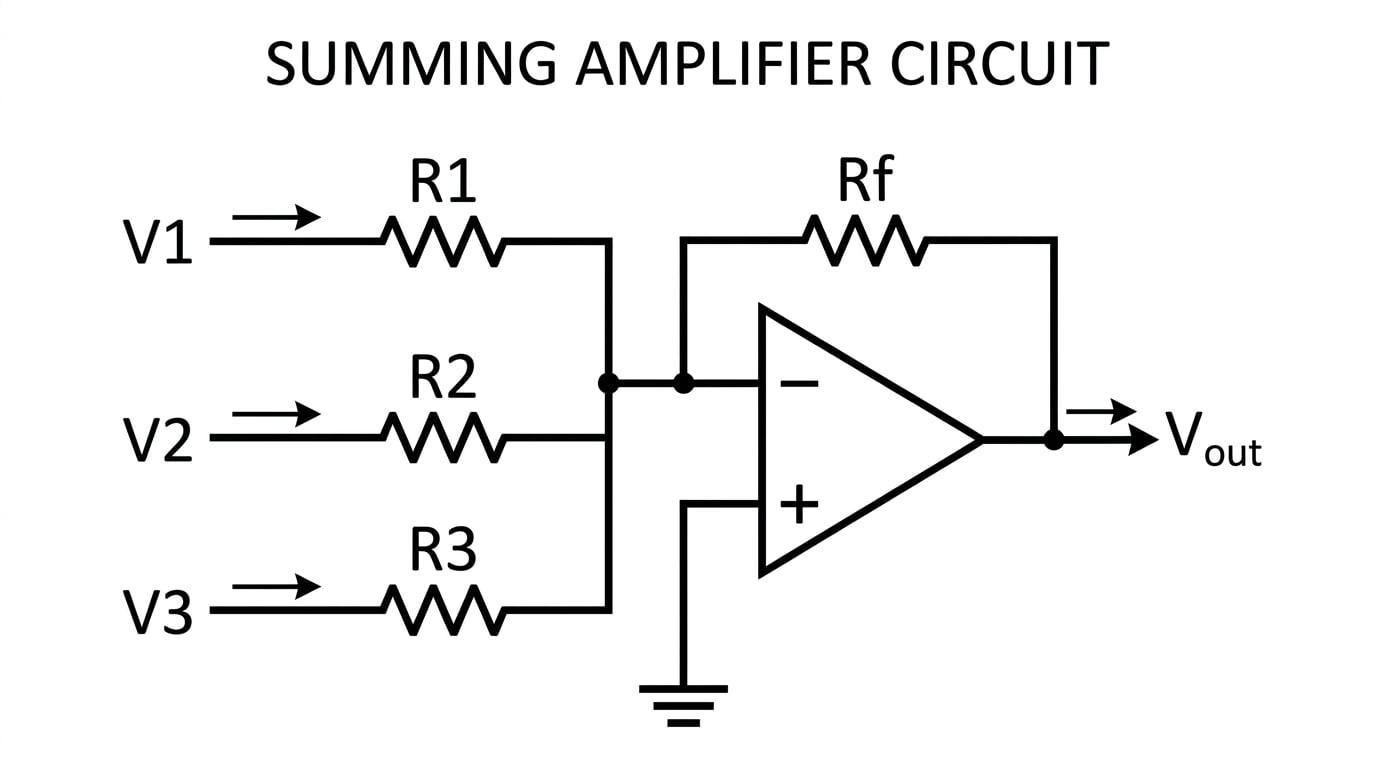
A summing amplifier is essentially an inverting amplifier that has been given extra inputs. It is widely used in audio mixing desks to combine the signals from several different microphones into one single output track.
How it Works (The Virtual Earth)
To understand how it works, we need to revisit the concept of the virtual earth.
In the diagram above, the non-inverting input (the +++ terminal) is connected directly to ground (0 V0 \text{ V}0 V). Because an ideal op-amp has infinite open-loop gain, the feedback loop forces the inverting input (the −-− terminal) to match this voltage. Therefore, the junction where all the input resistors meet is at 0 V0 \text{ V}0 V.
Because the junction is at 0 V0 \text{ V}0 V, the current flowing through each individual input branch depends only on its own input voltage and its own resistor. For example, the current from the first input is simply V1/R1V_1 / R_1V1/R1.
Summing Currents
By Kirchhoff's First Law, all the currents from the input branches meet at the virtual earth junction and add together. Because an ideal op-amp has infinite input resistance, absolutely zero current flows into the op-amp itself. Therefore, this entire combined current is forced to flow through the feedback resistor RfR_fRf.
The Summing Amplifier Formula
Because the total current flows through the feedback resistor RfR_fRf from the virtual earth (0 V0 \text{ V}0 V) to the output, the output voltage drops below zero. This gives us the standard formula for a summing amplifier:
Vout=−Rf(V1R1+V2R2+V3R3+… ) V_{\text{out}} = -R_f \left( \frac{V_1}{R_1} + \frac{V_2}{R_2} + \frac{V_3}{R_3} + \dots \right) Vout=−Rf(R1V1+R2V2+R3V3+…)You do not need to be able to derive this formula for your AQA exam, but you do need to know how to use it!
Missing the Minus Sign
It is incredibly easy to forget that the summing amplifier is based on the inverting amplifier circuit. Always remember to put the minus sign at the front of your formula, or your final voltage will have the wrong polarity!
Calculating a summed output
A summing amplifier has three inputs: V1=1.0 VV_1 = 1.0 \text{ V}V1=1.0 V, V2=2.0 VV_2 = 2.0 \text{ V}V2=2.0 V, and V3=−0.5 VV_3 = -0.5 \text{ V}V3=−0.5 V. The corresponding input resistors are R1=10 kΩR_1 = 10 \text{ k}\OmegaR1=10 kΩ, R2=20 kΩR_2 = 20 \text{ k}\OmegaR2=20 kΩ, and R3=5 kΩR_3 = 5 \text{ k}\OmegaR3=5 kΩ. The feedback resistor is Rf=50 kΩR_f = 50 \text{ k}\OmegaRf=50 kΩ. Calculate the output voltage, VoutV_{\text{out}}Vout.
- State the formula: Write down the summing amplifier equation exactly as it appears in the specification.
- Substitute the given values: Be careful to include the kΩ\text{k}\OmegakΩ multipliers (10310^3103) and watch out for the negative input voltage on V3V_3V3.
- Simplify and calculate: Notice that the 10310^3103 in the numerator and denominator cancel out, which makes the maths much cleaner.
The Difference Amplifier
Sometimes, rather than adding signals together, we want to subtract them.
Difference Amplifier
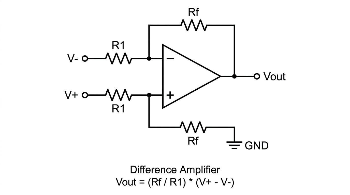
A difference amplifier is an operational amplifier circuit that amplifies the voltage difference between its two inputs, while rejecting any background voltage that is common to both of them.
This is highly useful in sensor circuits (like strain gauges or temperature bridges) where a tiny signal is sitting on top of a large, noisy background voltage. If both inputs experience the same noise, the difference amplifier subtracts the noise away completely.
The Difference Amplifier Formula
For a difference amplifier where the resistor ratios are balanced (as shown in the standard diagram above, where the resistors on the non-inverting side match the resistors on the inverting side), the output voltage is given by:
Vout=(V+−V−)RfR1 V_{\text{out}} = (V_+ - V_-) \frac{R_f}{R_1} Vout=(V+−V−)R1RfWhere:
- V+V_+V+ is the voltage applied to the non-inverting branch.
- V−V_-V− is the voltage applied to the inverting branch.
- RfR_fRf is the feedback resistor.
- R1R_1R1 is the input resistor.
Just like the summing amplifier, derivation of this formula is not required.
Supply Limits (Saturation)
Remember that the calculated output voltage VoutV_{\text{out}}Vout from these formulas is a purely theoretical value. In the real world, an op-amp is limited by its power supply. If your calculation produces an output of 25 V25 \text{ V}25 V but the op-amp is only powered by a ±15 V\pm 15 \text{ V}±15 V supply, the amplifier will saturate and the actual output will simply be +15 V+15 \text{ V}+15 V.
Finding the difference
A difference amplifier is connected to a power supply of ±12 V\pm 12 \text{ V}±12 V. The inputs are V+=4.2 VV_+ = 4.2 \text{ V}V+=4.2 V and V−=1.7 VV_- = 1.7 \text{ V}V−=1.7 V. The circuit uses resistors R1=10 kΩR_1 = 10 \text{ k}\OmegaR1=10 kΩ and Rf=100 kΩR_f = 100 \text{ k}\OmegaRf=100 kΩ. Calculate the theoretical output voltage and state the actual output voltage.
- State the formula:
- Substitute and find the theoretical output:
- Check against the supply limits: The theoretical output is 25 V25 \text{ V}25 V. However, the op-amp is limited by its ±12 V\pm 12 \text{ V}±12 V power supply. Because 25 V>12 V25 \text{ V} > 12 \text{ V}25 V>12 V, the amplifier saturates. The actual output voltage will therefore be +12 V+12 \text{ V}+12 V.
In the exam
- State the formula first: Always write out the formula exactly as it appears in the data booklet before plugging in numbers. This often secures your first method mark even if you make a calculator error later.
- Watch the kilo-ohms: Resistor values in op-amp circuits are almost always given in kΩ\text{k}\OmegakΩ. While they often cancel out in the summing/difference fractions, it is much safer to explicitly write ×103\times 10^3×10³ in your working to avoid silly mistakes.
- Always check for saturation: If an exam question explicitly provides the op-amp's supply voltages (e.g., ±15 V\pm 15 \text{ V}±15 V), it is usually a massive hint! Compare your final theoretical VoutV_{\text{out}}Vout to these limits and state clearly if the amplifier saturates.
Check yourself
- Why must the formula for a summing amplifier always include a minus sign?
- In a summing amplifier, what prevents the voltage from one input source "leaking" backward into the other input sources?
- If a difference amplifier has Rf=R1R_f = R_1Rf=R1, what does the formula for VoutV_{\text{out}}Vout simplify to?
- What happens to the actual output of an op-amp if the calculated VoutV_{\text{out}}Vout is larger than the positive power supply voltage?