Real operational amplifiers (A-level only)
What you'll learn in this topic:
- How real operational amplifiers (op-amps) differ from the "ideal" model.
- How to read and interpret the frequency response curve of an op-amp.
- How to calculate the trade-off between an amplifier's gain and its bandwidth using the gain-bandwidth product.
The illusion of the ideal op-amp
When you first learned about operational amplifiers, you used an "ideal" model to simplify the circuit calculations. You assumed the op-amp had infinite open-loop gain, infinite input resistance, and infinite bandwidth.
In reality, nothing is infinite. A real op-amp is built from dozens of microscopic transistors, resistors, and capacitors etched onto a silicon chip. These internal components impose physical limits on the op-amp's performance.
Open-loop gain
The open-loop gain is the voltage gain of the op-amp when there is no feedback loop connected from the output back to the input. For a real op-amp, this is extremely high (typically around 10510^5105) but not infinite.
Because the gain isn't truly infinite, the assumption that the two input terminals are at exactly the same potential (the "virtual earth" approximation in inverting amplifiers) is only an approximation, though usually a very good one. Real op-amps also have a tiny bit of input current (because input resistance is large, but not infinite) and some internal output resistance.
However, the most significant limitation you need to calculate in AQA Physics is the limitation on frequency.
The frequency response curve
An ideal op-amp would amplify a signal perfectly, regardless of whether the signal oscillates once a second or a billion times a second. In other words, it would have an infinite bandwidth.
Bandwidth
The bandwidth of an amplifier is the range of frequencies over which the amplifier provides a constant, reliable voltage gain. It is measured in hertz (Hz\text{Hz}Hz).
Real op-amps have tiny internal capacitances. Because the reactance of a capacitor changes with frequency, high-frequency signals essentially "leak" away inside the op-amp. As a result, the op-amp struggles to amplify very fast-changing signals. As the frequency of the input signal increases, the open-loop gain drops.
We can visualise this using a frequency response curve.
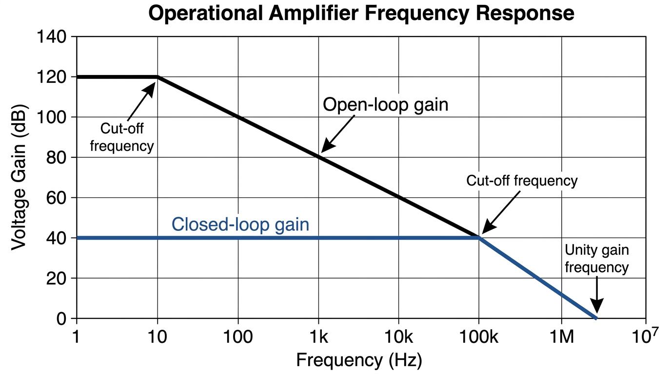
Notice two things about the open-loop gain curve:
- It is flat at very low frequencies, but only up to a few hertz (often just 10 Hz10 \text{ Hz}10 Hz).
- Beyond this low cut-off point, the gain falls steadily as frequency increases. (The axes are usually logarithmic, making this drop-off look like a straight line).
This means if you use an op-amp without any feedback, it can only amplify signals that are changing very slowly (like temperature sensors). If you tried to pass an audio signal (which goes up to 20 000 Hz20\,000 \text{ Hz}20000 Hz) through an open-loop op-amp, the high notes would be severely muffled because the gain drops to almost nothing at high frequencies!
Trading gain for bandwidth
To make op-amps useful for high-frequency signals like audio or radio, we use negative feedback. By connecting a portion of the output back to the inverting input, we deliberately reduce the amplifier's overall gain (known as the closed-loop gain).
Looking at the graph above, the horizontal "Closed-loop gain" line represents our amplifier after we have added negative feedback resistors.
Because we have lowered the gain, the flat portion of the line stretches out much further to the right. The amplifier can now maintain this lower, constant gain over a much wider range of frequencies before it hits the sloping open-loop line and begins to drop.
The Golden Rule of Real Op-amps
By using negative feedback to reduce the voltage gain, you proportionally increase the bandwidth. You are trading raw amplification power for a wider frequency range.
This trade-off is mathematically perfect for a given op-amp. The product of the gain and the bandwidth is a constant value.
Gain×Bandwidth=constant \text{Gain} \times \text{Bandwidth} = \text{constant} Gain×Bandwidth=constantThis constant is known as the Gain-Bandwidth Product (often abbreviated to GBP, though the AQA spec just uses the equation above). The constant is unique to the specific model of op-amp you are using.
Unity-gain bandwidth
The constant is numerically equal to the frequency at which the open-loop gain drops to exactly 111. You can see this on a frequency response curve by tracing the open-loop slope all the way down to the x-axis (where gain = 111).
Let's look at how AQA tests this concept.
Calculating closed-loop bandwidth
A real operational amplifier has an open-loop voltage gain of 2.0×1052.0 \times 10^52.0×10⁵. When operating open-loop, its bandwidth is 15 Hz15 \text{ Hz}15 Hz.
The operational amplifier is then connected in an inverting amplifier circuit with an input resistor of 10 kΩ10 \text{ k}\Omega10 kΩ and a feedback resistor of 450 kΩ450 \text{ k}\Omega450 kΩ.
Calculate the new bandwidth of the amplifier.
- Calculate the constant (Gain-Bandwidth Product) for the device. Using the open-loop characteristics:
- Calculate the new closed-loop voltage gain. Use the inverting amplifier gain formula (ignoring the negative sign, as bandwidth only cares about the magnitude of the gain):
- Calculate the new bandwidth. Rearrange the gain-bandwidth equation for the closed-loop circuit:
The new bandwidth is 67 kHz67 \text{ kHz}67 kHz (to 2 sig figs).
Forgetting that gain has no units
Remember that voltage gain is a ratio (Vout/VinV_{out} / V_{in}Vout/Vin), so it is a dimensionless number. Because of this, the "constant" in the gain×bandwidth\text{gain} \times \text{bandwidth}gain×bandwidth equation takes on the units of bandwidth, which is hertz (Hz\text{Hz}Hz). Do not invent a unit for gain!
In the exam
- If an exam question asks you to "explain the effect of negative feedback on the amplifier", always state two points: it reduces the voltage gain but increases the bandwidth.
- You may be asked to sketch or complete a frequency response curve. Remember to use straight lines (ruler!) for the slopes if the axes are logarithmic, and ensure your closed-loop line goes perfectly horizontal before meeting the open-loop slope.
- When using gain=RfRin\text{gain} = \frac{R_f}{R_{in}}gain=RinRf, use the magnitude (ignore the minus sign of the inverting amplifier) when plugging it into the gain-bandwidth product equation, as bandwidth cannot be negative.
Check yourself
- What happens to the open-loop gain of a real op-amp as the frequency of the input signal increases?
- Why is an open-loop op-amp unsuitable for amplifying an audio signal?
- If an op-amp has a gain-bandwidth product of 106 Hz10^6 \text{ Hz}106 Hz, what would the bandwidth be if the closed-loop gain is set to 100100100?