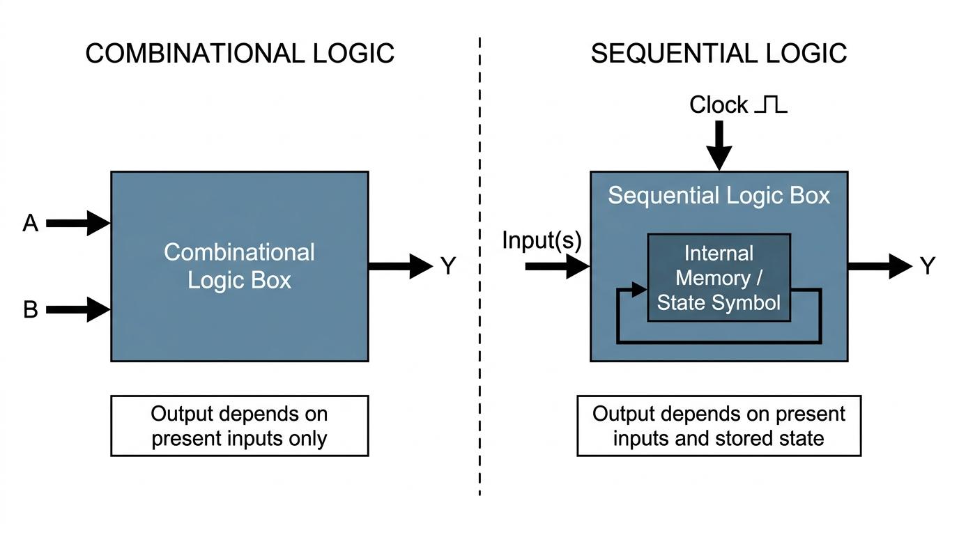
Welcome to the world of sequential logic! So far in electronics, you have probably focused on combinational logic (like AND, OR, and NOT gates), where the output depends only on what the inputs are doing right now. In this topic, we add memory to our circuits.
What you'll learn:
- The fundamental difference between sequential and combinational logic.
- How clock, reset, and up/down inputs control a counting circuit.
- How standard binary, BCD, and Johnson counters operate.
- How to design a custom modulo-nnn counter using basic logic gates.
What is Sequential Logic?
In a combinational logic circuit, if you change an input, the output responds immediately. However, many real-world systems need to "remember" what happened previously. A digital stopwatch, for instance, needs to remember that it was at 5 seconds so it knows to change to 6 seconds on the next tick.
Sequential Logic
A logic circuit where the output depends not only on the present inputs, but also on the past sequence of inputs. It requires some form of memory to store its current state.
For AQA Physics, you don't need to know the complex internal wiring of the flip-flops that make up this memory. Instead, you treat the entire counting circuit as a "building block" (a black box) and focus on its inputs and outputs.
Key Inputs to a Counter
A typical counting circuit has a few standard control inputs:
- Clock: This is the heartbeat of the circuit. It is a continuous square wave (an alternating signal of 0 V0\text{ V}0 V and 5 V5\text{ V}5 V). The counter only changes its state (e.g., counts up by one) when the clock signal changes—usually on the rising edge or falling edge of the pulse.
- Reset: A pin that, when activated (usually by receiving a logic
1), instantly forces all outputs back to0. It wipes the memory clean. - Up / Down: A directional control pin. If it is set to logic
1, the circuit might count up (0,1,2,3…0, 1, 2, 3 \dots0,1,2,3…). If set to logic0, the circuit counts down (3,2,1,0…3, 2, 1, 0 \dots3,2,1,0…).
The Clock
Without a clock pulse, a sequential circuit is frozen. The clock determines when the circuit evaluates its inputs and updates its outputs.
Outputs from a Counter
A basic NNN-bit binary counter will have NNN output pins, usually labelled Q0,Q1,Q2Q_0, Q_1, Q_2Q0,Q1,Q2, and so on.
- Q0Q_0Q0 is the Least Significant Bit (LSB), representing 202^020 (the 1s column).
- Q1Q_1Q1 represents 212^121 (the 2s column).
- Q2Q_2Q2 represents 222^222 (the 4s column).
A 4-bit counter has four outputs (Q0Q_0Q0 to Q3Q_3Q3) and can count from 0000 to 1111 in binary (which is 0 to 15 in decimal).
Modulo-nnn Counters
The word "modulo" simply refers to the number of distinct states the counter goes through before repeating.
A standard 4-bit binary counter goes through 16 states (0 to 15). Therefore, its natural state is a Modulo-16 counter. A 3-bit counter is naturally a Modulo-8 counter.
But what if we want a counter that counts from 0 up to 5, and then resets back to 0? We would need a Modulo-6 counter (since 0, 1, 2, 3, 4, 5 is exactly six states).
Building a Custom Modulo-nnn Counter
To create a Modulo-nnn counter from a standard binary counter, we must force the counter to reset the moment it tries to reach the number nnn.
Because logic gates operate almost instantaneously, if we wire the outputs that represent nnn into an AND gate, and connect the AND gate to the Reset pin, the counter will reach nnn for a fraction of a microsecond before immediately wiping itself back to 0.
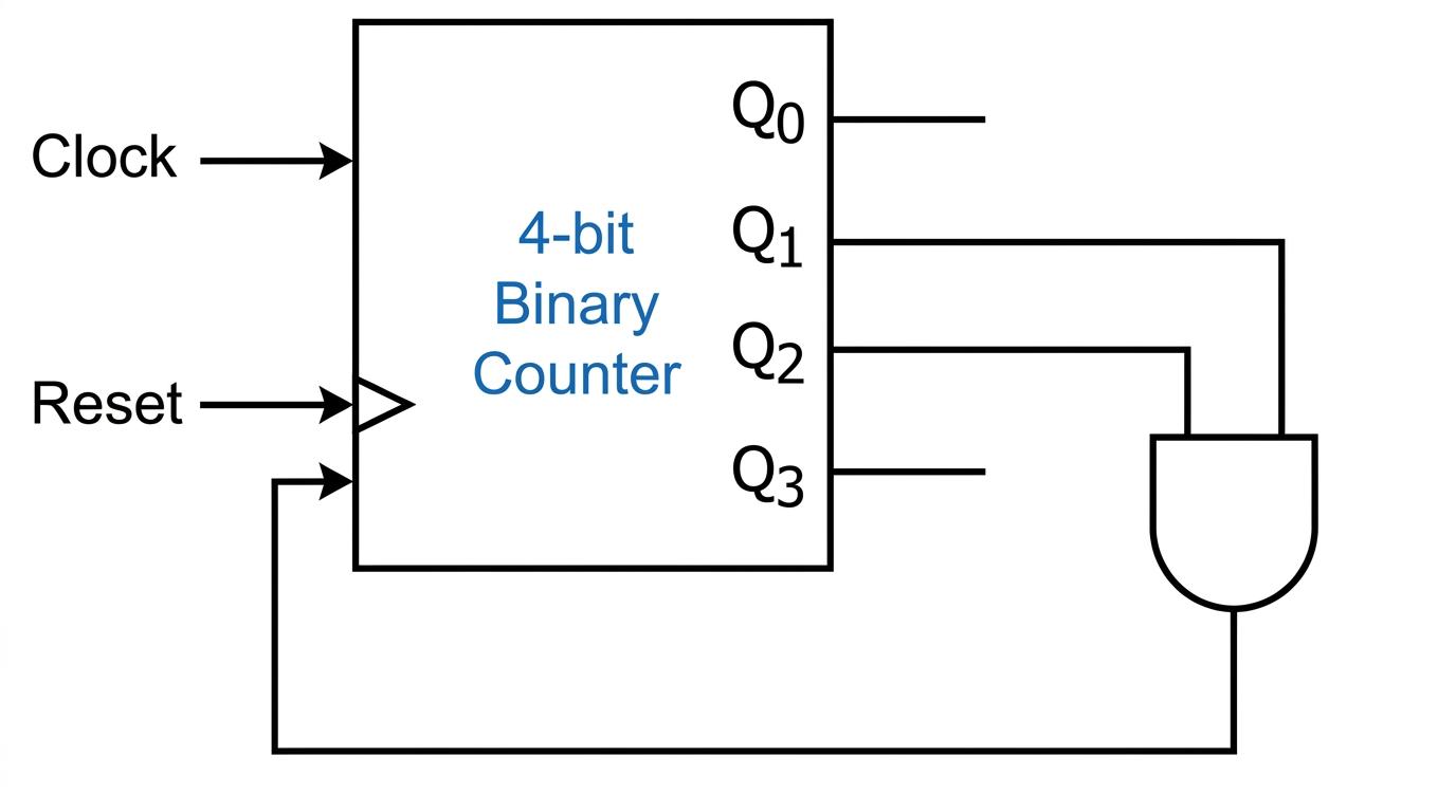
Let's look at how to design this step-by-step.
Designing a Modulo-12 counter
A student has a standard 4-bit binary counter with outputs Q0,Q1,Q2,Q3Q_0, Q_1, Q_2, Q_3Q0,Q1,Q2,Q3 and a Reset pin. They want to use logic gates to turn this into a Modulo-12 counter. State which outputs should be connected to the inputs of an AND gate to achieve this.
- First, determine the maximum value the counter should display. A Modulo-12 counter has 12 states, meaning it counts from 0 up to 11.
- The counter must reset the moment it hits the number 12. Convert 12 into a 4-bit binary number.
- In binary, 12=8+412 = 8 + 412=8+4.
- So, 121212 in binary is
1100(Q3=1,Q2=1,Q1=0,Q0=0Q_3=1, Q_2=1, Q_1=0, Q_0=0Q3=1,Q2=1,Q1=0,Q0=0). - Identify the outputs that are logic
1when the number is 12. These are Q3Q_3Q3 and Q2Q_2Q2. - Connect Q3Q_3Q3 and Q2Q_2Q2 to the inputs of an AND gate, and connect the output of the AND gate to the Reset pin. (When Q3Q_3Q3 and Q2Q_2Q2 are both
1, the AND gate outputs1, triggering the reset).
Resetting on the wrong number
A very common mistake is resetting on the maximum number you want to display. If you want to count from 0 to 5, do not wire the reset for 5. If you do, the counter will reset the instant it hits 5, meaning you'll only ever see 0, 1, 2, 3, 4. You must wire the reset for the next number (the modulus nnn).
BCD (Binary Coded Decimal) Counters
A BCD counter is simply a specific, very common type of custom counter. It is a Modulo-10 counter.
In human life, we count in base-10 (decimal). If we want to build a digital clock, we need a counter that counts from 0 to 9, and then resets back to 0 while sending a signal to the next digit.
A BCD counter uses a 4-bit binary counter but is wired internally to reset when it hits 10 (binary 1010).
- It counts:
0000, 0001, 0010 ... 1001. - On the 10th clock pulse, it resets to
0000.
BCD counters are widely used to drive 7-segment displays (the classic digital numbers on microwaves and alarm clocks).
Johnson Counters
A Johnson counter (sometimes called a twisted ring counter) is a completely different style of sequential counting circuit. Instead of counting up in standard binary numbers, it creates a repeating pattern of shifting bits.
It is built by placing several memory blocks (flip-flops) in a row. The output of each block feeds into the next, and the inverted output of the very last block loops all the way back to the start.
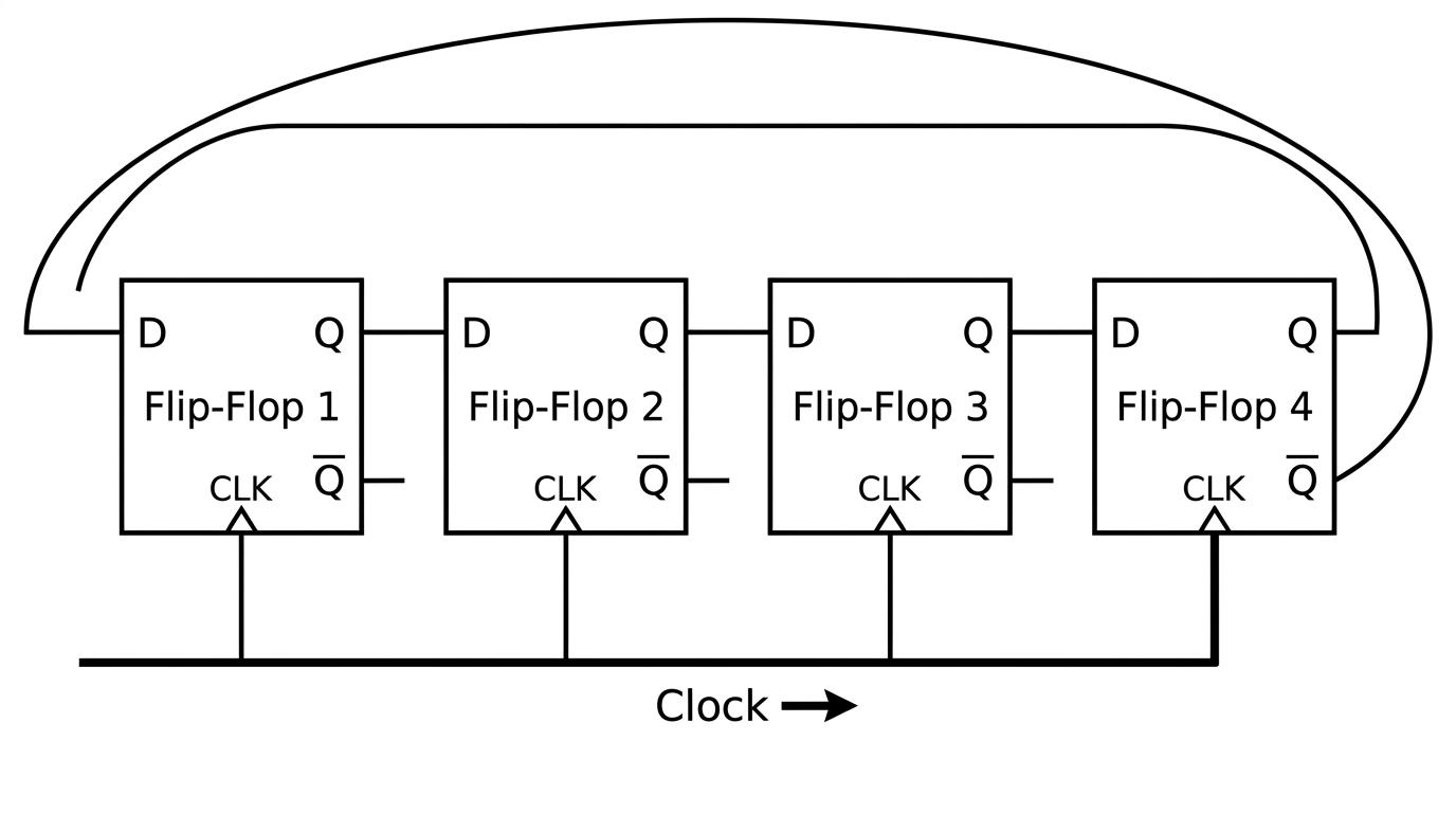
Because of this twisted feedback loop, the counter "fills up" with 1s from left to right, and then "empties out" with 0s from left to right.
Let's look at the sequence for a 4-bit Johnson counter, starting from an empty state (0000). On each clock pulse, the bits shift to the right. The new bit entering on the left is the opposite of whatever fell off the right-hand side.
- Start:
0000(The rightmost bit is 0. Its inverse is 1, which feeds to the front). - Pulse 1:
1000(The 1 enters the front, everything shifts right). - Pulse 2:
1100 - Pulse 3:
1110 - Pulse 4:
1111(The counter is now full of 1s. The rightmost bit is 1. Its inverse is 0, which now feeds to the front). - Pulse 5:
0111(The 0 enters the front, everything shifts right). - Pulse 6:
0011 - Pulse 7:
0001 - Pulse 8:
0000(We are back to the start!)
Johnson Counter States
A Johnson counter with NNN bits will have 2N2N2N distinct states in its sequence. So, a 4-bit Johnson counter is a Modulo-8 counter, and a 5-bit Johnson counter is a Modulo-10 counter.
Identifying the next state in a Johnson Counter
A 5-bit Johnson counter is currently in the state 11110. Determine the state of the counter after the next clock pulse.
- Note the current state:
11110. - In a Johnson counter, all bits shift one place to the right.
- The rightmost bit is currently
0. - The inverted value of the rightmost bit is fed back into the leftmost position. The inverse of
0is1. - Shift the first four bits (
1111) to the right, and put the new1at the far left. - The new state is
11111.
In the exam
When answering exam questions on sequential logic:
- Always check whether the question asks for a standard Binary counter, a BCD counter, or a Johnson counter. Their sequences are entirely different!
- If asked to draw or describe the logic for a Modulo-nnn counter, convert nnn to binary, pick out the
1s, and feed those specific QQQ outputs into an AND gate connected to the reset pin. - Remember that Q0Q_0Q0 is almost always the Least Significant Bit (202^020). Read the axis or table headers carefully so you don't wire Q0Q_0Q0 thinking it is Q3Q_3Q3.
Check yourself
- What is the fundamental difference between sequential logic and combinational logic?
- Which binary outputs would you connect to an AND gate to make a Modulo-10 (BCD) counter?
- If a 4-bit Johnson counter is currently in the state
0011, what will its state be after the next clock pulse?