Digital circuits are incredibly fast, but they need a "heartbeat" to keep all their components synchronised. If different parts of a computer system try to process data at slightly different times, the entire system crashes. This heartbeat is provided by a specific type of circuit called an astable.
What you'll learn:
- What an astable oscillator is and why digital systems need clock pulses.
- The anatomy of a clock pulse, including period, frequency, and pulse width.
- How to calculate the duty cycle and mark-to-space ratio of a signal.
- How to change the frequency of an astable using an external resistor-capacitor (RCRCRC) network.
What is an Astable?
Imagine trying to row a boat with eight people. Without a coxswain shouting "stroke... stroke...", everyone would row at their own pace, and the boat would go nowhere. In digital electronics, the "coxswain" is the astable.
Astable
An astable is a type of oscillator circuit that has no stable states. It continuously and automatically switches back and forth between a logic 1 (HIGH voltage) and a logic 0 (LOW voltage) without needing any external trigger.
Because it oscillates constantly, the output of an astable provides a continuous stream of square-wave voltage pulses. We call this stream a clock pulse. Every time the clock pulse ticks, the digital circuit moves to its next task.
The Anatomy of a Clock Pulse
To analyse an astable, we need to be able to describe the square wave it produces. We use a few very specific terms to map out the timing of the pulse.
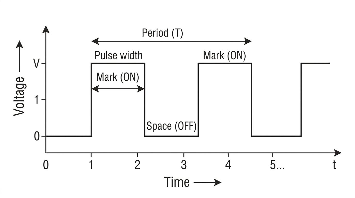
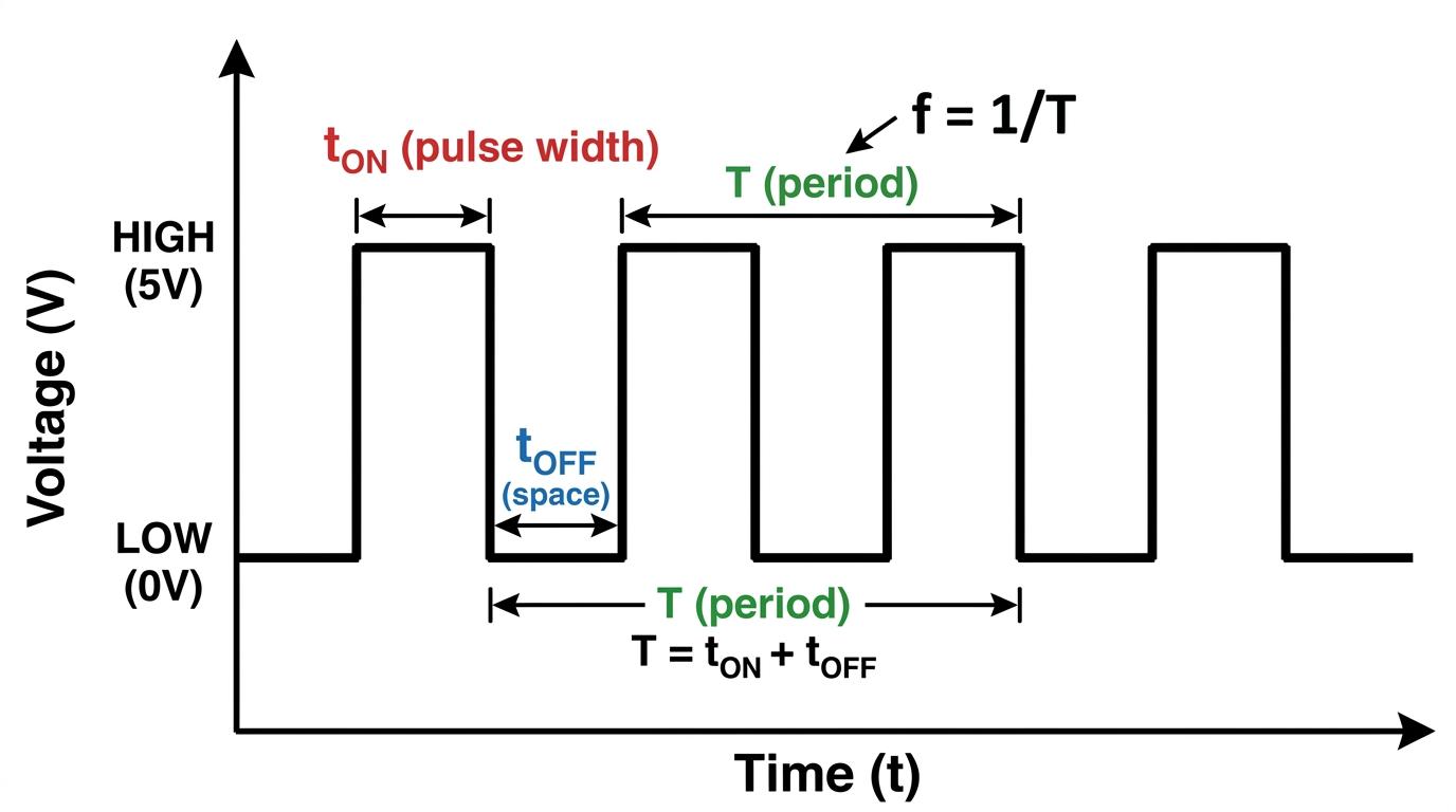
Clock pulse timings
- Mark (tONt_{\text{ON}}tON): The time the signal spends in the HIGH (logic 1) state. This is also called the pulse width.
- Space (tOFFt_{\text{OFF}}tOFF): The time the signal spends in the LOW (logic 0) state.
- Period (TTT): The total time taken for one complete cycle. It is the sum of the mark and the space: T=tON+tOFFT = t_{\text{ON}} + t_{\text{OFF}}T=tON+tOFF.
- Clock rate / Frequency (fff): The number of complete clock pulses per second, measured in hertz (Hz).
Just like in standard wave mechanics, the relationship between frequency and period is:
f=1T f = \frac{1}{T} f=T1Duty Cycle and Mark-to-Space Ratio
Engineers don't just care about how fast the clock is ticking; they also care about the shape of the pulse. A clock pulse doesn't have to be perfectly symmetrical (spending exactly half its time ON and half its time OFF).
We measure this shape in two different ways:
- Duty Cycle: This is the percentage of the total period that the signal is HIGH.
- Mark-to-Space Ratio: This is the direct ratio of the time spent HIGH compared to the time spent LOW.
Ratios vs Percentages
Students frequently confuse duty cycle with mark-to-space ratio.
- Duty Cycle compares the mark to the whole cycle (TTT).
- Mark-to-Space compares the mark to the space (tOFFt_{\text{OFF}}tOFF). If a signal is ON for 2 ms2\text{ ms}2 ms and OFF for 3 ms3\text{ ms}3 ms, the mark-to-space ratio is 2:32:32:3, but the duty cycle is 2/5=40%2/5 = 40\%2/5=40%.
Calculating clock pulse characteristics
An astable oscillator produces a clock pulse with a frequency of 5.0 kHz5.0\text{ kHz}5.0 kHz. The mark-to-space ratio is 1:31:31:3. Calculate the pulse width and the duty cycle of the signal.
- First, find the total period (TTT) of one cycle using the frequency.
- Use the mark-to-space ratio (1:31:31:3) to find the fraction of the total time spent in the mark (ON) state. The ratio has a total of 1+3=41 + 3 = 41+3=4 parts. The pulse width (tONt_{\text{ON}}tON) is 1 part out of 4.
- Calculate the duty cycle using the ratio of tONt_{\text{ON}}tON to TTT. Since we know it's 1 part out of 4 total parts, this is straightforward:
Controlling the Frequency with an RC Network
If you are designing a digital circuit, you will need to choose how fast the clock runs. The astable itself is just a switching mechanism; to control when it switches, we connect an external resistor-capacitor (RCRCRC) network.
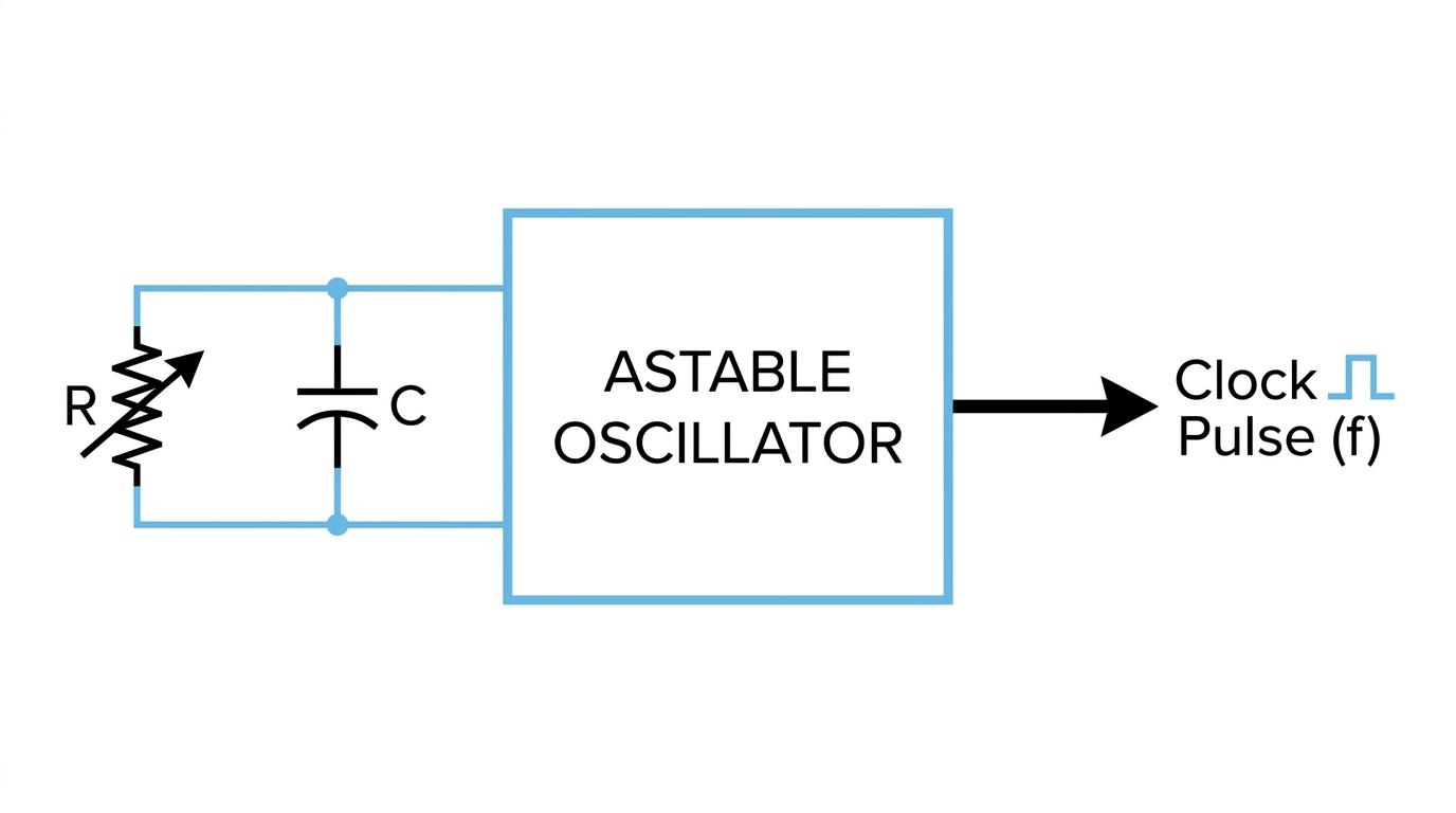
Inside the astable, the circuit monitors the voltage across the external capacitor.
- The capacitor charges up through the resistor until it hits a certain upper threshold voltage, causing the astable to switch its output to LOW.
- The capacitor then discharges until it hits a lower threshold voltage, causing the astable to switch its output back to HIGH.
Because the charging and discharging times depend entirely on the time constant (τ=RC\tau = RCτ=RC), changing the value of the external resistor or capacitor changes the frequency of the clock pulse.
Frequency and RC values
The period (TTT) of an astable oscillator is directly proportional to the product of the external resistance and capacitance:
T∝RC T \propto RC T∝RCConsequently, the frequency (fff) is inversely proportional to RCRCRC:
f∝1RC f \propto \frac{1}{RC} f∝RC1Increasing the resistance or the capacitance increases the time it takes to charge/discharge, which lengthens the period and lowers the frequency.
Don't panic about the 555 timer
You might see older textbooks or practical guides talking heavily about the internal workings of the "555 timer chip" (a very famous astable IC). You do not need to know this. The AQA specification explicitly states that knowledge of a particular circuit or specific device like the 555 chip is not required. You only need to know that an external RCRCRC network controls the frequency!
Varying the RC network
An astable circuit with an external capacitance of 1.0 \muF1.0\text{ \mu F}1.0 \muF and an external resistance of 22 kΩ22\text{ k}\Omega22 kΩ produces a clock rate of 60 Hz60\text{ Hz}60 Hz. The resistor is swapped out for a 33 kΩ33\text{ k}\Omega33 kΩ resistor. Assuming the internal thresholds of the astable remain identical, what is the new clock rate?
- State the proportional relationship between frequency and the RCRCRC values.
- Set up a ratio to compare the new frequency (f2f_2f2) to the old frequency (f1f_1f1). Since CCC remains constant, it cancels out of the ratio.
- Substitute the given values to find the new frequency.
In the exam
- Watch out for micro and milli: Pulse widths are almost always tiny. Expect values in milliseconds (ms\text{ms}ms, 10−310^{-3}10−3) and microseconds (\mus\text{\mu s}\mus, 10−610^{-6}10−6). Always convert to standard SI seconds (s\text{s}s) before doing f=1/Tf = 1/Tf=1/T calculations.
- Read the graph carefully: If given an oscilloscope trace, ensure you identify whether the horizontal axis gives the period or just the mark/pulse width. Don't just grab the first number you see to calculate frequency.
- Proportionality is your friend: For RCRCRC network questions, you rarely need a complex formula. If resistance doubles, the period doubles, so the frequency halves. Use simple ratio mathematics (as shown in the second example) to save time.
Check yourself
- Can you define the difference between the "mark" and the "space" of a clock pulse?
- If a square wave has a duty cycle of 50%50\%50%, what is its mark-to-space ratio?
- If you wanted to make a clock pulse tick faster (higher frequency), what two changes could you make to the external RCRCRC network?