Combinational logic (A-level only)
Combinational logic is the foundation of digital digital signal processing. In combinational circuits, the output depends only on the current state of the inputs—there is no "memory" of what happened in the past.
What you'll learn:
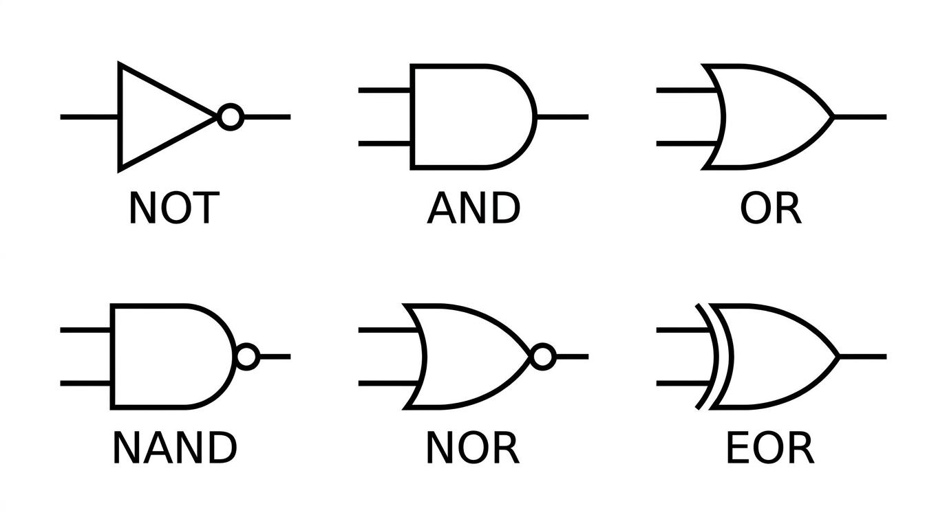
- The functions and symbols of standard logic gates (AND, OR, NOT, NAND, NOR, and EOR).
- How to represent logic circuits using Boolean algebra.
- How to deduce a truth table from a combination of logic gates.
- How to design a logic circuit from scratch to match a specific truth table.
The Logic Gate Building Blocks
Before we build circuits, we need to understand the individual building blocks. A logic gate is a physical electronic device that makes a simple logical decision based on the signals fed into it. In digital electronics, signals are either ON or OFF, which we represent as 1 and 0.
Truth Table
A table showing every possible combination of input states (1s and 0s) to a logic gate or circuit, alongside the corresponding output state.
Here are the six standard logic gates you need to know:
- NOT gate (Inverter): Has exactly one input. It flips the signal. If the input is 0, the output is 1. If the input is 1, the output is 0.
- AND gate: The output is 1 only if both input one AND input two are 1. Otherwise, the output is 0.
- OR gate: The output is 1 if either input one OR input two (or both) are 1.
- NAND gate (NOT-AND): The exact opposite of an AND gate. The output is 0 only if both inputs are 1. In all other cases, it outputs 1.
- NOR gate (NOT-OR): The exact opposite of an OR gate. The output is 1 only if both inputs are 0.
- EOR gate (Exclusive-OR): The output is 1 if the inputs are different from each other (one is 1, the other is 0).
Boolean Algebra
Drawing gate symbols every time you want to analyze a complex circuit gets messy. Instead, physicists and engineers use Boolean algebra to write logic operations as mathematical equations.
In Boolean algebra, variables like AAA and BBB can only take the values 0 or 1. We use specific symbols for the three fundamental gates:
- NOT: Represented by a bar over the letter. "NOT A" is written as Aˉ\bar{A}Aˉ.
- AND: Represented by a dot (like multiplication). "A AND B" is written as A⋅BA \cdot BA⋅B.
- OR: Represented by a plus sign (like addition). "A OR B" is written as A+BA + BA+B.
Remembering the symbols
Think of AND as multiplication: 1⋅1=11 \cdot 1 = 11⋅1=1, but 1⋅0=01 \cdot 0 = 01⋅0=0. Think of OR as addition (mostly): 1+0=11 + 0 = 11+0=1, and 0+1=10 + 1 = 10+1=1. Just remember that in Boolean logic, 1+1=11 + 1 = 11+1=1 (since 1 is the maximum value, representing "ON", it doesn't become 2).
You can combine these basic mathematical operators to represent the other composite gates:
- NAND: A⋅B‾\overline{A \cdot B}A⋅B (first you AND them, then you invert the entire result).
- NOR: A+B‾\overline{A + B}A+B (first you OR them, then invert).
- EOR: A⋅Bˉ+Aˉ⋅BA \cdot \bar{B} + \bar{A} \cdot BA⋅Bˉ+Aˉ⋅B (either AAA is true and BBB is false, OR AAA is false and BBB is true).
Deducing a Circuit's Output
Exam questions frequently give you a diagram of several interconnected gates and ask you to find the final output or complete a truth table. The trick is to break the circuit down into intermediate stages, writing a Boolean expression for each wire as you go.
Deducing a truth table from a logic circuit
Imagine a circuit with three inputs, AAA, BBB, and CCC. Inputs AAA and BBB feed into an OR gate. The output of that OR gate (which we'll call XXX) feeds into one input of an AND gate. Input CCC feeds into the other input of that same AND gate. The final output from the AND gate is QQQ.
Determine the Boolean expression for QQQ and deduce its truth table.
- Write the Boolean expression for the first gate. The OR gate takes AAA and BBB, so its output is X=A+BX = A + BX=A+B.
- Write the Boolean expression for the final gate. The AND gate takes XXX and CCC, so the output is Q=X⋅CQ = X \cdot CQ=X⋅C.
- Substitute the intermediate expression XXX into the final one to get the complete equation: Q=(A+B)⋅CQ = (A + B) \cdot CQ=(A+B)⋅C.
- Set up a truth table with columns for all inputs (AAA, BBB, CCC), the intermediate point (XXX), and the final output (QQQ). Since there are 3 inputs, there are 23=82^3 = 823=8 possible combinations (rows).
- Calculate the value of XXX for each row. The column for XXX will be 1 if A=1A=1A=1 or B=1B=1B=1.
- Calculate the value of QQQ for each row. The column for QQQ will be 1 only if X=1X=1X=1 and C=1C=1C=1.
| A | B | C | X | Q |
|---|---|---|---|---|
| 0 | 0 | 0 | 0 | 0 |
| 0 | 0 | 1 | 0 | 0 |
| 0 | 1 | 0 | 1 | 0 |
| 0 | 1 | 1 | 1 | 1 |
| 1 | 0 | 0 | 1 | 0 |
| 1 | 0 | 1 | 1 | 1 |
| 1 | 1 | 0 | 1 | 0 |
| 1 | 1 | 1 | 1 | 1 |
Order of operations in logic
Just like standard algebra, brackets are critical. (A+B)⋅C(A + B) \cdot C(A+B)⋅C is completely different from A+(B⋅C)A + (B \cdot C)A+(B⋅C). The first means "A OR B, then AND the result with C". The second means "B AND C, then OR the result with A". Always use brackets when translating a circuit into Boolean algebra to preserve the correct order of the logic gates!
Constructing a Circuit from a Truth Table
Often, the process is reversed: you are given a truth table (perhaps representing the rules for a safety alarm system) and asked to design the logic circuit that produces it.
While you can sometimes "spot" the logic, the most reliable and systematic method is the Sum of Products technique.
Sum of Products Method
Look only at the rows in the truth table where the final output is 1. For each of these rows, write an AND expression that is true only for that exact combination of inputs. Finally, combine all of these separate AND expressions together using OR gates.
Designing a logic circuit
Design a circuit using basic building block gates (AND, OR, NOT) that matches the following truth table:
| A | B | Q |
|---|---|---|
| 0 | 0 | 1 |
| 0 | 1 | 0 |
| 1 | 0 | 0 |
| 1 | 1 | 1 |
- Identify the rows where the final output QQQ is 1. Here, that happens in the first row and the fourth row.
- Write an AND expression for the first row. We need an expression that is 1 only when A=0A=0A=0 and B=0B=0B=0. To achieve this, we must invert both inputs before ANDing them together: Aˉ⋅Bˉ\bar{A} \cdot \bar{B}Aˉ⋅Bˉ.
- Write an AND expression for the fourth row. We need an expression that is 1 only when A=1A=1A=1 and B=1B=1B=1. This is simply A⋅BA \cdot BA⋅B.
- Combine the expressions from step 2 and step 3 using an OR operation. This gives our final Boolean equation: Q=(Aˉ⋅Bˉ)+(A⋅B)Q = (\bar{A} \cdot \bar{B}) + (A \cdot B)Q=(Aˉ⋅Bˉ)+(A⋅B).
- Translate this final Boolean expression into a circuit diagram.
- Branch input AAA and pass it through a NOT gate to get Aˉ\bar{A}Aˉ.
- Branch input BBB and pass it through a NOT gate to get Bˉ\bar{B}Bˉ.
- Connect Aˉ\bar{A}Aˉ and Bˉ\bar{B}Bˉ into an AND gate.
- Connect the original AAA and BBB into a separate AND gate.
- Take the outputs of both AND gates and connect them into a final OR gate to produce QQQ.
Note: You might recognise that the truth table in the example above is an Exclusive-NOR (the exact opposite of EOR), but building it from standard AND/OR/NOT blocks demonstrates exactly how any arbitrary truth table can be turned into a working circuit.
In the exam
- When evaluating a pre-drawn circuit diagram, always pencil in the logic state (0 or 1) or the Boolean expression at intermediate points directly on the wires.
- If asked to draw a logic circuit, make sure your gate symbols are distinctly drawn. Examiners cannot award marks if they can't tell your AND gate from your OR gate (OR gates should have a distinctly curved input side and a pointed output tip).
- Check your final constructed circuit by running one "ON" condition and one "OFF" condition from the truth table back through your drawing to ensure it produces the expected output.
Check yourself
- If a NAND gate has inputs A=1A=1A=1 and B=0B=0B=0, what is the output?
- How would you write the Boolean expression for an OR gate where both inputs have first been passed through NOT gates?
- Why is it helpful to add extra columns to a truth table when analyzing a circuit with multiple connected gates?