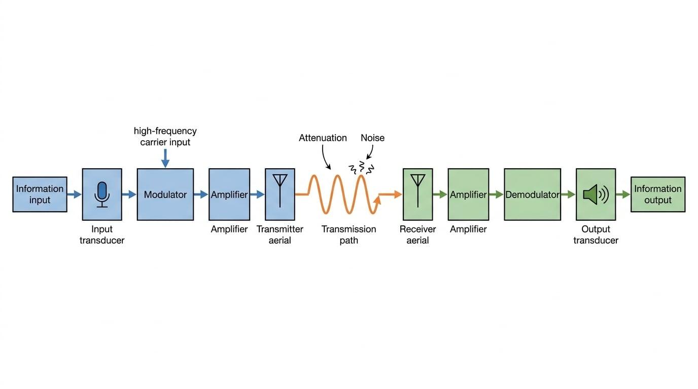
Welcome to the world of communication systems! Whether you are making a phone call, listening to live radio, or streaming a live broadcast, you are relying on a continuous, real-time flow of data.
What you'll learn:
- The layout of the standard block diagram for a real-time communication system.
- The specific sequence of stages in both the transmitter and the receiver.
- The precise purpose of each component (such as the modulator and demodulator) in getting a signal from A to B.
What is a "Real-Time" Communication System?
A real-time communication system transfers information almost instantaneously. When you speak into a microphone, the person at the other end hears your voice with only a tiny fraction of a second's delay (the time it takes the signal to physically travel through wires or space).
To make this happen, we need three main physical sections:
- The Transmitter: Takes the raw information, turns it into an electrical signal, packages it up, and blasts it out.
- The Transmission Path: The physical gap the signal has to cross (like the air, a vacuum, a copper wire, or a fibre optic cable).
- The Receiver: Catches the incoming signal, unpacks it, and turns it back into a format humans (or computers) can understand.

Let's break down the exact sequence of blocks you need to know for your AQA exam, moving from left to right.
Part 1: The Transmitter Sequence
The transmitter's job is to prepare your information so it can survive the journey across the transmission path. It follows a strict four-step sequence.
1. Information Input & Input Transducer
You can't send a sound wave or a physical picture directly through a radio antenna. First, we need to convert the physical information into an electrical signal.
Transducer
A device that converts one form of energy into another. In communications, an input transducer specifically converts non-electrical energy (like sound or light) into an electrical signal.
For a voice call, the information input is the sound wave of your voice, and the input transducer is a microphone. The microphone outputs a weak, low-frequency electrical signal (often called the baseband or information signal).
2. The Modulator
This is arguably the cleverest part of the system. The raw electrical signal from the microphone is usually a low-frequency wave. Low-frequency electromagnetic waves are terrible at traveling long distances, and they would require an antenna miles long to transmit properly!
To fix this, the system generates a very high-frequency carrier wave.
The Paper and the Rock
Imagine trying to throw a flat piece of paper (your low-frequency information signal) across a windy field. It won't go far.
Now, imagine wrapping that paper around a heavy rock (the high-frequency carrier wave) and throwing it. The rock cuts through the air and carries the paper easily. At the other end, your friend unwraps the paper to read the message and drops the rock.
The modulator is the device that "wraps the paper around the rock". Its purpose is to superimpose the information signal onto a high-frequency carrier wave.
3. The Amplifier (Transmitter side)
Once the signal is modulated, it is still just a weak electrical voltage inside a circuit. If we fed it directly to an antenna, the emitted wave wouldn't even reach the end of your street.
The amplifier increases the power (and amplitude) of the modulated electrical signal.
4. The Transmitter
Finally, the boosted, modulated electrical signal reaches the transmitter (for example, a transmitting aerial/antenna). Its purpose is to convert the electrical signal into a wave that can travel through the chosen medium (such as an electromagnetic radio wave radiating into space).
Exam-style question: Explaining transmitter stages
Question: In a radio broadcasting system, state the purpose of the modulator and the amplifier in the transmitter section. (2 marks)
- Address the modulator: State clearly what it combines. "The modulator superimposes the low-frequency audio signal onto a high-frequency carrier wave."
- Address the amplifier: State what property it increases. "The amplifier increases the power (or amplitude) of the modulated signal before transmission."
Part 2: The Transmission Path
The transmission path is the link between the transmitter and the receiver. Depending on the system, this could be:
- Free space (for radio waves and microwaves)
- Copper cables (for electrical signals)
- Optical fibres (for pulses of light)
Signal Degradation
As a signal travels through any transmission path, it loses energy (called attenuation) and picks up unwanted random background signals (called noise). By the time it reaches the receiver, the signal is incredibly weak.
Part 3: The Receiver Sequence
The signal has arrived, but it is weak and still "wrapped around the rock". The receiver must undo everything the transmitter did, in the correct order.
1. The Receiver
The receiver (e.g., a receiving aerial) intercepts the wave from the transmission path and converts it back into a weak alternating electrical signal.
2. The Amplifier (Receiver side)
Because the signal suffered attenuation in the transmission path, the very first thing we must do is boost it. The receiver's amplifier increases the voltage of the very weak received signal so that it is strong enough to be processed by the rest of the circuitry.
Confusing the two amplifiers
Notice that there are two amplifiers in the full system!
- The transmitter's amplifier boosts a strong signal to a massive power level so it can be blasted across the country.
- The receiver's amplifier takes an incredibly tiny, microscopic signal and boosts it just enough so the circuits can read it.
Always specify which amplifier you are talking about in an exam!
3. The Demodulator
Now we have a strong electrical signal, but it is still modulated (the information is still riding on the high-frequency carrier wave).
The demodulator acts as a filter. Its purpose is to extract the original low-frequency information signal and discard the high-frequency carrier wave.
4. Output Transducer & Information Output
We finally have our original electrical information signal back. But humans can't hear electrical voltages!
The signal enters an output transducer (like a loudspeaker or a screen), which converts the electrical signal back into the original non-electrical format (sound waves or light). You, the listener, then receive the information output.
Exam-style question: Identifying receiver stages
A block diagram of a radio receiver shows an aerial connected to block X, which connects to block Y, which connects to a loudspeaker. Question: Identify block X and block Y, and state the purpose of block Y. (3 marks)
- Locate the sequence: The standard sequence after the receiving aerial is Amplifier →\to→ Demodulator →\to→ Output transducer.
- Identify the blocks: Therefore, block X must be the amplifier and block Y must be the demodulator.
- State the purpose of Y: The purpose of the demodulator is to separate (or extract) the original information signal from the high-frequency carrier wave.
Putting it all together
If you are asked to draw or label the complete system, always double-check your order. A good trick is to look for the symmetry:
Symmetry of the system
The system is perfectly mirrored around the transmission path!
- Edge: Transducers (Input at the start, Output at the end).
- Middle: Modulation (Modulator wraps it, Demodulator unwraps it).
- Inner: Amplifiers (Boost before sending, Boost after receiving).
- Center: Transmitter →\to→ Transmission Path →\to→ Receiver.
In the exam
- Learn the precise verbs: Examiners look for specific words. Transducers convert. Modulators superimpose. Amplifiers increase power/amplitude. Demodulators extract or separate.
- Don't skip the obvious: If a question asks for the whole block diagram, don't forget the very first and very last arrows: "Information input" and "Information output". They are explicitly listed in the AQA specification!
- Context matters: If the question is about a radio station, give context. Say "the input transducer, such as a microphone..." or "the output transducer, such as a loudspeaker...".
Check yourself
- Can you list all 5 stages of the transmitter section in order, starting from 'Information input'?
- Why is it necessary to have an amplifier in the receiver section?
- What is the difference in purpose between a modulator and a demodulator?
- If the output transducer is a loudspeaker, what form of energy is it converting the electrical signal into?