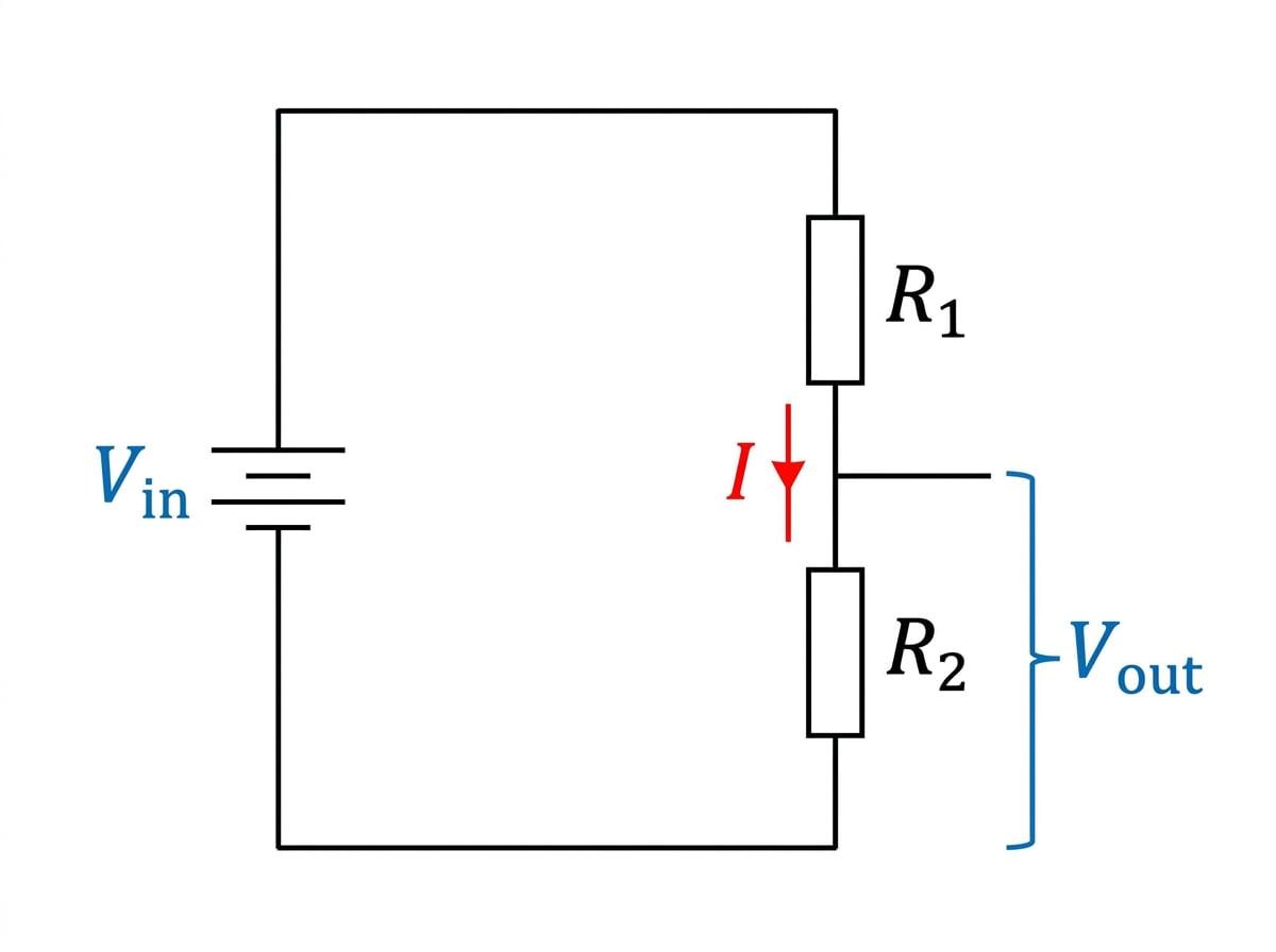
Welcome to one of the most useful and commonly examined circuits in A-Level Physics! In this topic, we will look at how we can "divide" a voltage to get exactly the potential difference we need.
What you'll learn:
- What a potential divider is and how it shares a source voltage.
- How to use the potential divider equation to calculate output voltages.
- How to design variable supplies using variable resistors.
- How to build sensor circuits that respond to temperature (using thermistors) or light (using LDRs).
What is a potential divider?
A potential divider is exactly what it sounds like: a circuit that takes an input voltage and divides it up.
In its simplest form, a potential divider consists of two resistors connected in series across a power supply. You already know from your earlier studies of series circuits that the total potential difference (p.d.) of the supply is shared between the components.
Potential divider
A circuit consisting of two or more components connected in series across a power supply, used to supply a specific, chosen fraction of the source potential difference.
If you have a 12 V12 \text{ V}12 V battery, but you only want to supply 4 V4 \text{ V}4 V to a specific component, you can't just plug it directly into the battery. Instead, you can use a potential divider to "tap off" exactly 4 V4 \text{ V}4 V.
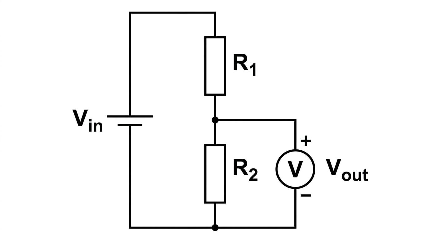
In the diagram above, the input voltage VinV_{\text{in}}Vin is applied across both resistors, R1R_1R1 and R2R_2R2. The output voltage VoutV_{\text{out}}Vout is taken across just one of them (in this case, R2R_2R2).
The Golden Rule of Potential Dividers
The voltage is shared in the same ratio as the resistances. The resistor with the larger resistance will always take a larger share of the total input voltage.
The Potential Divider Equation
We can calculate the exact output voltage using the potential divider equation.
Since the components are in series, the same current III flows through both. The total resistance is R1+R2R_1 + R_2R1+R2, so the current is:
I=VinR1+R2 I = \frac{V_{\text{in}}}{R_1 + R_2} I=R1+R2VinThe output voltage VoutV_{\text{out}}Vout is simply the p.d. across R2R_2R2, which is I×R2I \times R_2I×R2. Substituting our expression for current gives us the standard potential divider equation:
Vout=R2R1+R2Vin V_{\text{out}} = \frac{R_2}{R_1 + R_2} V_{\text{in}} Vout=R1+R2R2VinThis formula is incredibly useful. The fraction R2R1+R2\frac{R_2}{R_1 + R_2}R1+R2R2 simply represents R2R_2R2's "share" of the total resistance.
Calculating the output voltage
A 9.0 V9.0 \text{ V}9.0 V battery is connected in series with a 20Ω20 \Omega20Ω resistor and a 40Ω40 \Omega40Ω resistor. An output is taken across the 40Ω40 \Omega40Ω resistor. Calculate the output voltage.
- Identify the variables from the question: We are given Vin=9.0 VV_{\text{in}} = 9.0 \text{ V}Vin=9.0 V. Let the top resistor be R1=20ΩR_1 = 20 \OmegaR1=20Ω and the bottom resistor (where we are taking the output) be R2=40ΩR_2 = 40 \OmegaR2=40Ω.
- Write down the potential divider equation:
- Substitute the values and solve:
Sanity Check
Before doing the math, look at the ratio. 40Ω40 \Omega40Ω is twice as big as 20Ω20 \Omega20Ω. Therefore, it should get twice as much voltage. The total voltage (9.0 V9.0 \text{ V}9.0 V) splits into 3.0 V3.0 \text{ V}3.0 V and 6.0 V6.0 \text{ V}6.0 V. Since the output is across the larger resistor, 6.0 V6.0 \text{ V}6.0 V makes perfect sense!
Variable Potential Dividers
Sometimes we don't just want a fixed output voltage; we want to be able to adjust it smoothly (like a volume dial on a stereo, or a dimmer switch).
We can achieve this by replacing the two fixed resistors with a single variable resistor that has a sliding contact (often called a potentiometer, though the AQA spec notes you don't need to know how to use one as a measuring instrument).
Imagine a single long resistive track. By moving a slider up and down this track, you are effectively splitting it into two sections: R1R_1R1 (above the slider) and R2R_2R2 (below the slider).
- If you move the slider up, R1R_1R1 decreases and R2R_2R2 increases. Because R2R_2R2 now makes up a larger fraction of the total resistance, VoutV_{\text{out}}Vout increases.
- If you move the slider down, R2R_2R2 approaches zero, so VoutV_{\text{out}}Vout drops towards 0 V0 \text{ V}0 V.
This allows you to provide a continuously variable p.d. from 0 V0 \text{ V}0 V all the way up to VinV_{\text{in}}Vin.
Sensor Circuits: Thermistors and LDRs
This is where potential dividers get really clever. Instead of a manual slider, what if we use a component whose resistance changes based on the environment?
By replacing one of the resistors with a thermistor or a Light Dependent Resistor (LDR), the output voltage will automatically rise and fall as the temperature or light level changes. We have built a sensor!
Using an NTC Thermistor
AQA focuses on Negative Temperature Coefficient (NTC) thermistors.
- As temperature increases, the resistance of the thermistor decreases.
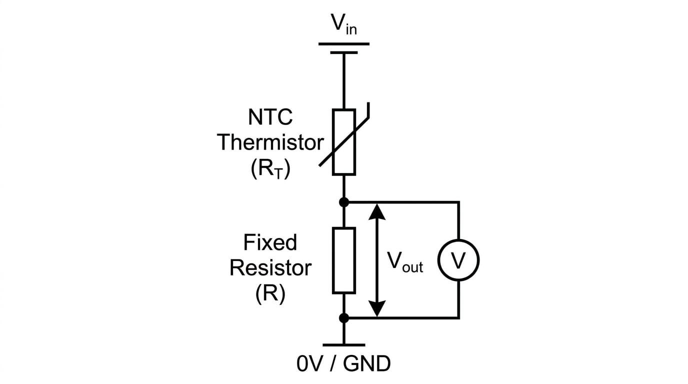
Look at the diagram above. The thermistor is in the R1R_1R1 position, and a fixed resistor is in the R2R_2R2 position. If the room gets hotter:
- The resistance of the thermistor (R1R_1R1) drops.
- The total resistance of the circuit (R1+R2R_1 + R_2R1+R2) decreases.
- The fixed resistor (R2R_2R2) now represents a larger share of the total resistance.
- Therefore, the output voltage VoutV_{\text{out}}Vout (which is across R2R_2R2) increases.
This circuit could be used to switch on a cooling fan when it gets too hot!
Using an LDR
LDRs work similarly, but with light:
- As light intensity increases, the resistance of the LDR decreases.
If you place an LDR in the R1R_1R1 (top) position, VoutV_{\text{out}}Vout across R2R_2R2 will increase as it gets brighter. If you swap them—putting the LDR in the R2R_2R2 (bottom) position—then as it gets brighter, R2R_2R2's resistance drops, so its share of the voltage drops, and VoutV_{\text{out}}Vout will decrease. This second setup is perfect for automatically turning on streetlights when it gets dark!
Ratio thinking
If you ever get confused about whether VoutV_{\text{out}}Vout goes up or down, just ask yourself: "What is happening to the resistance of the component I am measuring across?" If its resistance goes down (relative to the rest of the circuit), its voltage share goes down. If its resistance goes up, its voltage share goes up.
Analyzing a sensor circuit
A potential divider consists of a 12 V12 \text{ V}12 V power supply, an NTC thermistor (top component), and a fixed resistor of 5.0 kΩ5.0 \text{ k}\Omega5.0 kΩ (bottom component). The output is taken across the fixed resistor. At 10∘C10^\circ\text{C}10∘C, the thermistor has a resistance of 15 kΩ15 \text{ k}\Omega15 kΩ. At 40∘C40^\circ\text{C}40∘C, its resistance drops to 2.5 kΩ2.5 \text{ k}\Omega2.5 kΩ. Calculate the change in output voltage as the temperature rises from 10∘C10^\circ\text{C}10∘C to 40∘C40^\circ\text{C}40∘C.
- Calculate VoutV_{\text{out}}Vout at 10∘C10^\circ\text{C}10∘C: The thermistor R1=15 kΩR_1 = 15 \text{ k}\OmegaR1=15 kΩ. The fixed resistor R2=5.0 kΩR_2 = 5.0 \text{ k}\OmegaR2=5.0 kΩ.
- Calculate VoutV_{\text{out}}Vout at 40∘C40^\circ\text{C}40∘C: The thermistor R1R_1R1 is now 2.5 kΩ2.5 \text{ k}\Omega2.5 kΩ. R2R_2R2 is still 5.0 kΩ5.0 \text{ k}\Omega5.0 kΩ.
- Calculate the change in voltage:
Forgetting to convert units
Watch out for kilo-ohms (kΩ\text{k}\OmegakΩ) and mega-ohms (MΩ\text{M}\OmegaMΩ). In the ratio R2R1+R2\frac{R_2}{R_1 + R_2}R1+R2R2, the powers of 10 will actually cancel out as long as R1R_1R1 and R2R_2R2 are in the same units. But it's always safest to convert everything to standard Ohms (Ω\OmegaΩ) before substituting them into the equation to avoid silly calculation errors.
In the exam
- Always check where VoutV_{\text{out}}Vout is measured. Do not blindly assume VoutV_{\text{out}}Vout is always across the bottom component. Read the text and look at the diagram. If the output is across the top resistor R1R_1R1, the numerator in your formula must be R1R_1R1.
- Look out for loaded dividers. The potential divider equation assumes that no current flows out of the VoutV_{\text{out}}Vout terminals. If the question states you connect a voltmeter with a finite resistance, or another component, across VoutV_{\text{out}}Vout, that component is now in parallel with R2R_2R2. You must first calculate the new combined resistance of R2R_2R2 and the component before finding the voltage!
- Use the phrase "share of the total resistance". When asked to explain why an output voltage changes in a sensor circuit, examiners love it when you state that "the component's resistance drops, so its share of the total resistance drops, leading to a smaller share of the supply p.d.".
Check yourself
- If a potential divider is made of two identical resistors, what is the output voltage across one of them compared to the input voltage?
- An LDR and a fixed resistor are in series. The output is taken across the LDR. Does the output voltage increase or decrease as the room gets darker?
- Write down the potential divider equation from memory. What does the denominator (R1+R2R_1 + R_2R1+R2) represent?