Electromagnetic induction (A-level only)
Welcome to electromagnetic induction! So far, you've learned that passing an electric current through a wire creates a magnetic field. In this topic, we are going to look at the reverse process: using magnetic fields to generate electricity. This is the underlying physics behind almost all the electricity generated on Earth.
What you'll learn:
- How moving a magnet or a wire can induce an electromotive force (emf).
- The two grand rules of induction: Faraday's Law and Lenz's Law.
- How to calculate the emf generated by an aeroplane flying through the Earth's magnetic field.
- How spinning a coil in a magnetic field creates an alternating current.
Simple Experimental Phenomena
Imagine you connect a simple coil of wire to a sensitive voltmeter (or galvanometer). If the coil is just sitting on the desk, the reading is zero.
But what happens if you pick up a bar magnet and push its north pole into the coil?
- While the magnet is moving in, the needle deflects (say, to the right), showing a voltage is being generated.
- When you stop moving the magnet, the needle instantly drops back to zero.
- When you pull the magnet out, the needle deflects in the opposite direction (to the left).
- If you move the magnet faster, the needle deflects further.
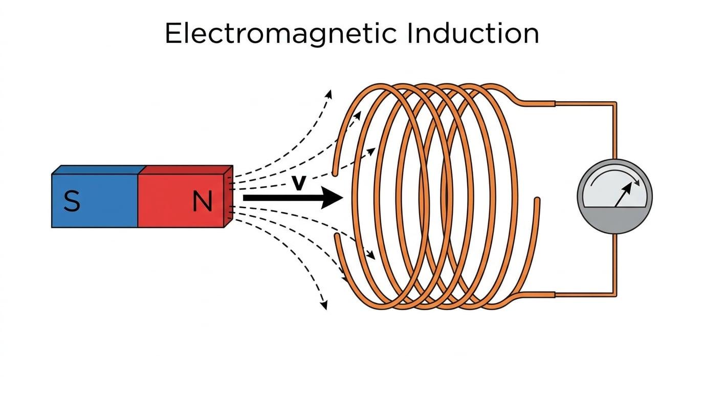
We call the voltage generated an induced emf.
Induced emf
An electromotive force (emf) generated in a circuit when the magnetic flux linking the circuit changes. If the circuit is closed, this emf will drive an induced current.
The crucial takeaway from these simple experiments is that change is required. A stationary magnet inside a coil does absolutely nothing. The magnetic field passing through the coil must be changing to induce an emf.
Faraday's Law and Flux Linkage
To put numbers to these phenomena, we need to bring back two terms from earlier in the Magnetic Fields topic:
- Magnetic Flux (Φ\PhiΦ): The total magnetic field passing through a given area, calculated as Φ=BA\Phi = BAΦ=BA (where BBB is flux density and AAA is the area perpendicular to the field). It is measured in webers (Wb).
- Magnetic Flux Linkage (NΦN\PhiNΦ): Simply the magnetic flux multiplied by the number of turns NNN in a coil. It is calculated as NΦ=BANN\Phi = BANNΦ=BAN and is measured in weber-turns (Wb turns).
When you push a magnet into a coil, the magnetic flux linkage increases. When you pull it out, it decreases. This continuous change is what causes the induced emf, a relationship summarised by Michael Faraday.
Faraday's Law of Electromagnetic Induction
The magnitude of the induced emf is directly proportional to the rate of change of magnetic flux linkage.
Mathematically, AQA provides this equation for the magnitude of the induced emf:
ε=NΔΦΔt \varepsilon = N \frac{\Delta \Phi}{\Delta t} ε=NΔtΔΦWhere:
- ε\varepsilonε is the magnitude of the induced emf in volts (V\text{V}V)
- NNN is the number of turns on the coil
- ΔΦ\Delta \PhiΔΦ is the change in magnetic flux in webers (Wb\text{Wb}Wb)
- Δt\Delta tΔt is the time taken in seconds (s\text{s}s)
Calculating emf using Faraday's Law
A circular coil of wire has 500500500 turns and a cross-sectional area of 4.0×10⁻³ m24.0 \times 10^{-3} \text{ m}^24.0×10⁻³ m2. A uniform magnetic field perpendicular to the plane of the coil increases steadily from 0 T0 \text{ T}0 T to 0.85 T0.85 \text{ T}0.85 T in a time of 0.20 s0.20 \text{ s}0.20 s. Calculate the magnitude of the induced emf across the ends of the coil.
- Calculate the initial and final magnetic flux (Φ\PhiΦ). Initial flux, Φinitial=BinitialA=0×(4.0×10−3)=0 Wb\Phi_{\text{initial}} = B_{\text{initial}} A = 0 \times (4.0 \times 10^{-3}) = 0 \text{ Wb}Φinitial=BinitialA=0×(4.0×10−3)=0 Wb Final flux, Φfinal=BfinalA=0.85×(4.0×10−3)=3.4×10⁻³ Wb\Phi_{\text{final}} = B_{\text{final}} A = 0.85 \times (4.0 \times 10^{-3}) = 3.4 \times 10^{-3} \text{ Wb}Φfinal=BfinalA=0.85×(4.0×10−3)=3.4×10⁻³ Wb
- Find the change in flux (ΔΦ\Delta \PhiΔΦ). ΔΦ=Φfinal−Φinitial=3.4×10⁻³ Wb\Delta \Phi = \Phi_{\text{final}} - \Phi_{\text{initial}} = 3.4 \times 10^{-3} \text{ Wb}ΔΦ=Φfinal−Φinitial=3.4×10⁻³ Wb
- Apply Faraday's Law using the formula ε=NΔΦΔt\varepsilon = N \frac{\Delta \Phi}{\Delta t}ε=NΔtΔΦ.
The magnitude of the induced emf is 8.5 V8.5 \text{ V}8.5 V.
Lenz's Law
Faraday's Law tells us the size of the induced emf, but we also noticed that pushing a magnet in causes a deflection in one direction, and pulling it out causes a deflection in the other.
Why does the current flow in the specific direction that it does? Nature is stubborn—it always tries to resist the change you are making.
Lenz's Law
The direction of the induced emf (and therefore the induced current) is always such as to oppose the change that caused it.
Imagine pushing the north pole of a magnet into a coil. The changing flux induces a current. According to Lenz's law, that current will flow in a direction that turns the near end of the coil into a North pole to repel the incoming magnet. You have to do mechanical work to push the magnet against this repulsion.
If you pull the north pole away, the current reverses, turning the near end of the coil into a South pole to attract the magnet back. Again, you must do mechanical work to separate them.
Conservation of Energy
Lenz's Law is a direct consequence of the principle of conservation of energy. If the induced current aided the change (e.g. by pulling the magnet in faster), the magnet would accelerate infinitely, creating electrical energy out of nothing! Instead, the electrical energy generated comes from the mechanical work you do in pushing or pulling the magnet against the opposing force.
Because of Lenz's law, the formal mathematical version of Faraday's Law includes a negative sign:
ε=−NΔΦΔt \varepsilon = - N \frac{\Delta \Phi}{\Delta t} ε=−NΔtΔΦThe AQA specification mostly asks you to calculate the magnitude using the positive version, but you must know what the negative sign represents.
A Straight Conductor Moving in a Magnetic Field
Induction doesn't just happen in coils. If you take a single straight wire and sweep it through a magnetic field (cutting across the field lines), an emf is induced across the ends of the wire.
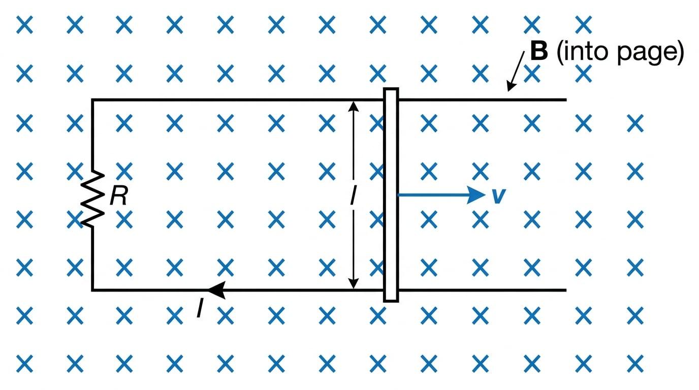
Imagine a straight metal rod of length lll moving at a constant velocity vvv perpendicular to a uniform magnetic field BBB.
In a time Δt\Delta tΔt, the rod moves a distance s=vΔts = v \Delta ts=vΔt. The area "swept out" by the rod is ΔA=l×s=lvΔt\Delta A = l \times s = l v \Delta tΔA=l×s=lvΔt. The change in magnetic flux is ΔΦ=BΔA=BlvΔt\Delta \Phi = B \Delta A = B l v \Delta tΔΦ=BΔA=BlvΔt.
Applying Faraday's Law (for a single wire, N=1N=1N=1):
ε=ΔΦΔt=BlvΔtΔt \varepsilon = \frac{\Delta \Phi}{\Delta t} = \frac{B l v \Delta t}{\Delta t} ε=ΔtΔΦ=ΔtBlvΔtThe Δt\Delta tΔt cancels out, leaving us with a beautiful, simple formula:
ε=Blv \varepsilon = B l v ε=BlvWhere:
- ε\varepsilonε is the induced emf (V\text{V}V)
- BBB is the magnetic flux density (T\text{T}T)
- lll is the length of the conductor in the field (m\text{m}m)
- vvv is the velocity of the conductor (m s−1\text{m s}^{-1}m s−1)
Perpendicular components only
This formula only works if the wire, the field, and the direction of motion are mutually perpendicular (all at 90° to each other). If the wire is moving parallel to the field lines, it isn't "cutting" them, so ΔΦ=0\Delta \Phi = 0ΔΦ=0 and no emf is induced!
The Aeroplane Question
An aeroplane has a wingspan of 36 m36 \text{ m}36 m and is flying horizontally due north at a speed of 250 m s−1250 \text{ m s}^{-1}250 m s−1. In this region, the Earth's magnetic field has a vertical component of 4.5×10⁻⁵ T4.5 \times 10^{-5} \text{ T}4.5×10⁻⁵ T downwards. Calculate the emf induced between the wingtips of the aeroplane.
- Identify the parameters. The wingspan acts as the straight conductor, so l=36 ml = 36 \text{ m}l=36 m. The velocity v=250 m s−1v = 250 \text{ m s}^{-1}v=250 m s−1. The flux density being "cut" by horizontal flight is the vertical component, B=4.5×10−5 TB = 4.5 \times 10^{-5} \text{ T}B=4.5×10⁻⁵ T.
- Check for perpendicularity. The wings are horizontal (East-West), the velocity is horizontal (North), and the field is vertical (Down). All three are mutually perpendicular.
- Calculate the emf using ε=Blv\varepsilon = B l vε=Blv.
The induced emf is 0.41 V0.41 \text{ V}0.41 V (to 2 s.f.).
Rotating Coil in a Magnetic Field (The Generator)
If we want to generate electricity continuously, moving a straight wire back and forth is inefficient. Instead, power stations use rotating coils.
When a flat rectangular coil rotates uniformly in a uniform magnetic field, the angle θ\thetaθ between the field lines and the normal to the coil changes constantly.
Remember that flux linkage depends on the angle: NΦ=BANcosθN\Phi = BAN \cos \thetaNΦ=BANcosθ. If the coil rotates with a constant angular speed ω\omegaω, the angle at any time ttt is θ=ωt\theta = \omega tθ=ωt. So, the flux linkage at any moment is:
NΦ=BANcos(ωt) N\Phi = BAN \cos(\omega t) NΦ=BANcos(ωt)According to Faraday's law, the emf is the rate of change (the derivative) of this flux linkage. If you differentiate BANcos(ωt)BAN \cos(\omega t)BANcos(ωt) with respect to time ttt (and apply the negative sign from Lenz's law), you get:
ε=BANωsin(ωt) \varepsilon = BAN\omega \sin(\omega t) ε=BANωsin(ωt)You don't need to be able to reproduce the calculus derivation in the exam, but you must be able to use the final equation!
Where:
- ε\varepsilonε is the induced emf at time ttt (V\text{V}V)
- BBB is the magnetic flux density (T\text{T}T)
- AAA is the cross-sectional area of the coil (m2\text{m}^2m2)
- NNN is the number of turns
- ω\omegaω is the angular speed of the coil (rad s−1\text{rad s}^{-1}rad s−1)
- ttt is the time elapsed (s\text{s}s)
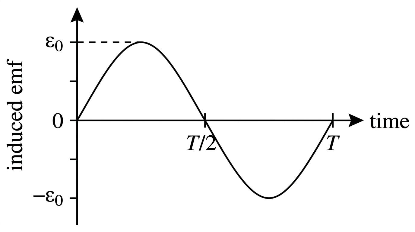
Look at the equation: it is a sine wave! This explains why spinning a coil generates alternating current (ac).
The maximum possible value of sin(ωt)\sin(\omega t)sin(ωt) is 111. Therefore, the peak emf (the maximum voltage generated, often written as ε0\varepsilon_{0}ε0) happens when the coil is perfectly parallel to the field lines (cutting them fastest), and its value is simply the constants clustered at the front of the formula:
Peak emf (ε0)=BANω \text{Peak emf } (\varepsilon_{0}) = BAN\omega Peak emf (ε0)=BANωAngular speed vs Frequency
AQA often gives you the rotational speed as a frequency fff in hertz (revolutions per second) or rpm (revolutions per minute). You must convert this to angular speed ω\omegaω in radians per second using ω=2πf\omega = 2\pi fω=2πf before plugging it into the equation.
Generator Peak Voltage
A bicycle dynamo features a rectangular coil of 120120120 turns and dimensions 4.0 cm4.0 \text{ cm}4.0 cm by 5.0 cm5.0 \text{ cm}5.0 cm. It rotates in a uniform magnetic field of flux density 0.15 T0.15 \text{ T}0.15 T at a steady rate of 151515 revolutions per second. Calculate the maximum (peak) emf induced in the coil.
- Calculate the area AAA in standard units (m2\text{m}^2m2). A=0.040 m×0.050 m=2.0×10⁻³ m2A = 0.040 \text{ m} \times 0.050 \text{ m} = 2.0 \times 10^{-3} \text{ m}^2A=0.040 m×0.050 m=2.0×10⁻³ m2
- Calculate the angular speed ω\omegaω. The frequency is f=15 Hzf = 15 \text{ Hz}f=15 Hz. ω=2πf=2×π×15=30π rad s−1\omega = 2 \pi f = 2 \times \pi \times 15 = 30\pi \text{ rad s}^{-1}ω=2πf=2×π×15=30π rad s−1 (approx 94.2 rad s−194.2 \text{ rad s}^{-1}94.2 rad s−1)
- Calculate the peak emf. The peak emf formula is ε0=BANω\varepsilon_{0} = BAN\omegaε0=BANω.
The peak emf is 3.4 V3.4 \text{ V}3.4 V (to 2 s.f.).
In the exam
- Look for keywords: If a question mentions "rate of change", it's a huge hint to use Faraday's Law (ε=NΔΦΔt\varepsilon = N \frac{\Delta \Phi}{\Delta t}ε=NΔtΔΦ).
- State the laws correctly: If asked to "state Faraday's law", you must include the word "magnitude" and "rate of change of flux linkage". Missing "linkage" or "rate of" will cost you the mark.
- Check for conservation of energy: If asked to explain why a falling magnet slows down when passing through a copper tube, use Lenz's law. State that the induced current creates an opposing magnetic field, and that the loss of kinetic energy (slowing down) accounts for the electrical energy generated.
- Calculator mode: If you are calculating an instantaneous emf using ε=BANωsin(ωt)\varepsilon = BAN\omega \sin(\omega t)ε=BANωsin(ωt), make absolutely sure your calculator is set to Radians, not Degrees! The ωt\omega tωt term is an angle in radians.
Check yourself
- Can you define magnetic flux linkage and state its SI unit?
- What is the difference between Faraday's Law and Lenz's Law?
- If a wire is moving exactly parallel to magnetic field lines, what is the induced emf?
- How does the peak emf of a rotating generator change if you double the speed of rotation?