Figure 1 shows a type of NOT gate called a Schmitt Trigger. This is connected to a capacitor of capacitance CCC and a resistor of resistance RRR to make an oscillator circuit. The circuit is used to produce continuous clock pulses.
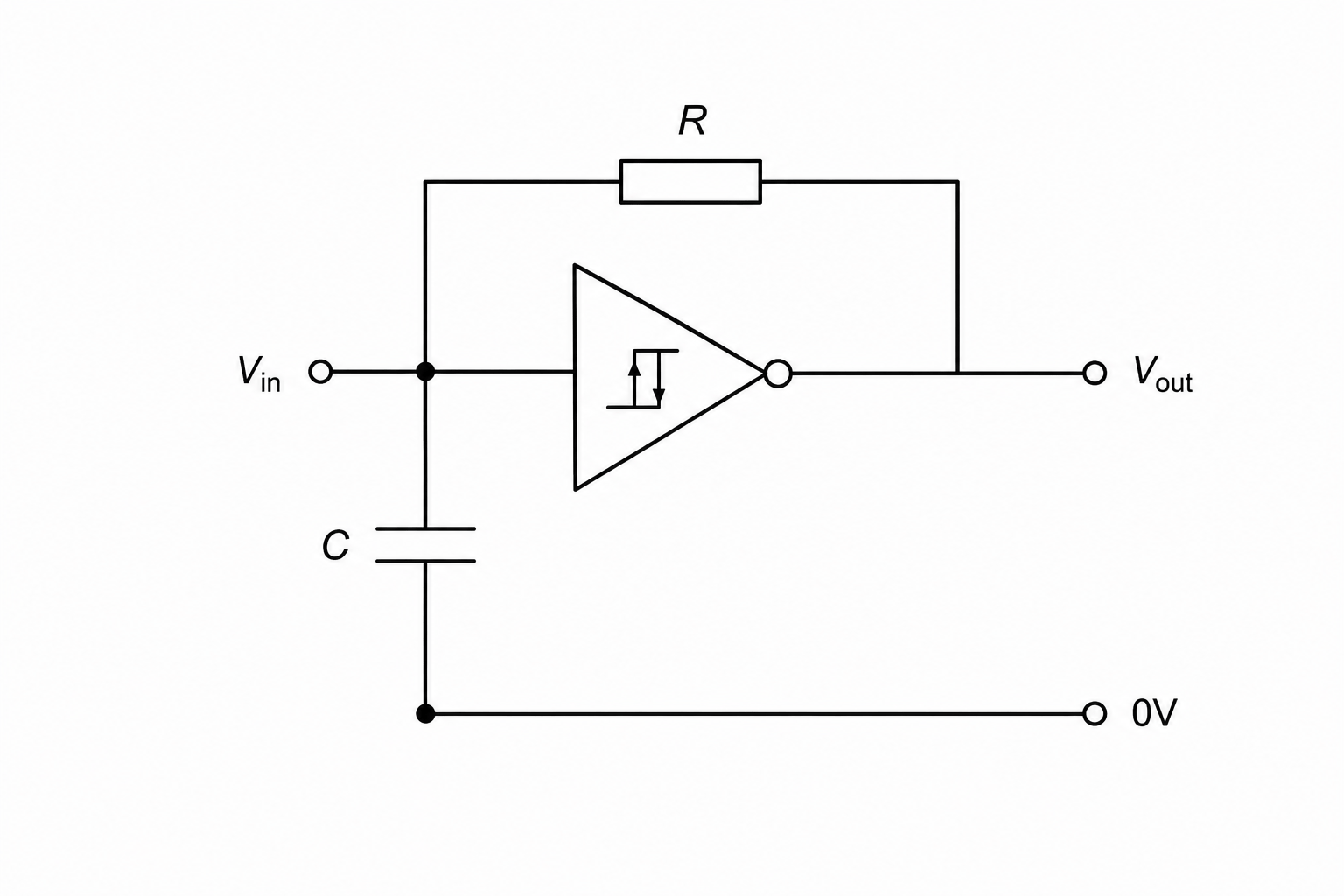
The output voltage VoutV_{\text{out}}Vout switches HIGH or LOW when the input voltage VinV_{\text{in}}Vin passes through one of two trigger voltage values.
The output voltage VoutV_{\text{out}}Vout switches to:
- LOW when VinV_{\text{in}}Vin rises and reaches the upper trigger voltage VUV_UVU
- HIGH when VinV_{\text{in}}Vin falls and reaches the lower trigger voltage VLV_LVL
Initially the capacitor is fully discharged and VinV_{\text{in}}Vin is at the lower trigger voltage VLV_LVL.
Explain the sequence of actions of this circuit as the output goes through one full cycle. The first two stages have been done for you.
You should refer to the RCRCRC circuit in Figure 1 and to VUV_UVU and VLV_LVL in your answer.
- Stage 1: Since VinV_{\text{in}}Vin is at VLV_LVL, the output VoutV_{\text{out}}Vout switches to HIGH.
- Stage 2: The capacitor now charges through the resistor, making VinV_{\text{in}}Vin rise.
- Stage 3:
- Stage 4:
- Stage 5:
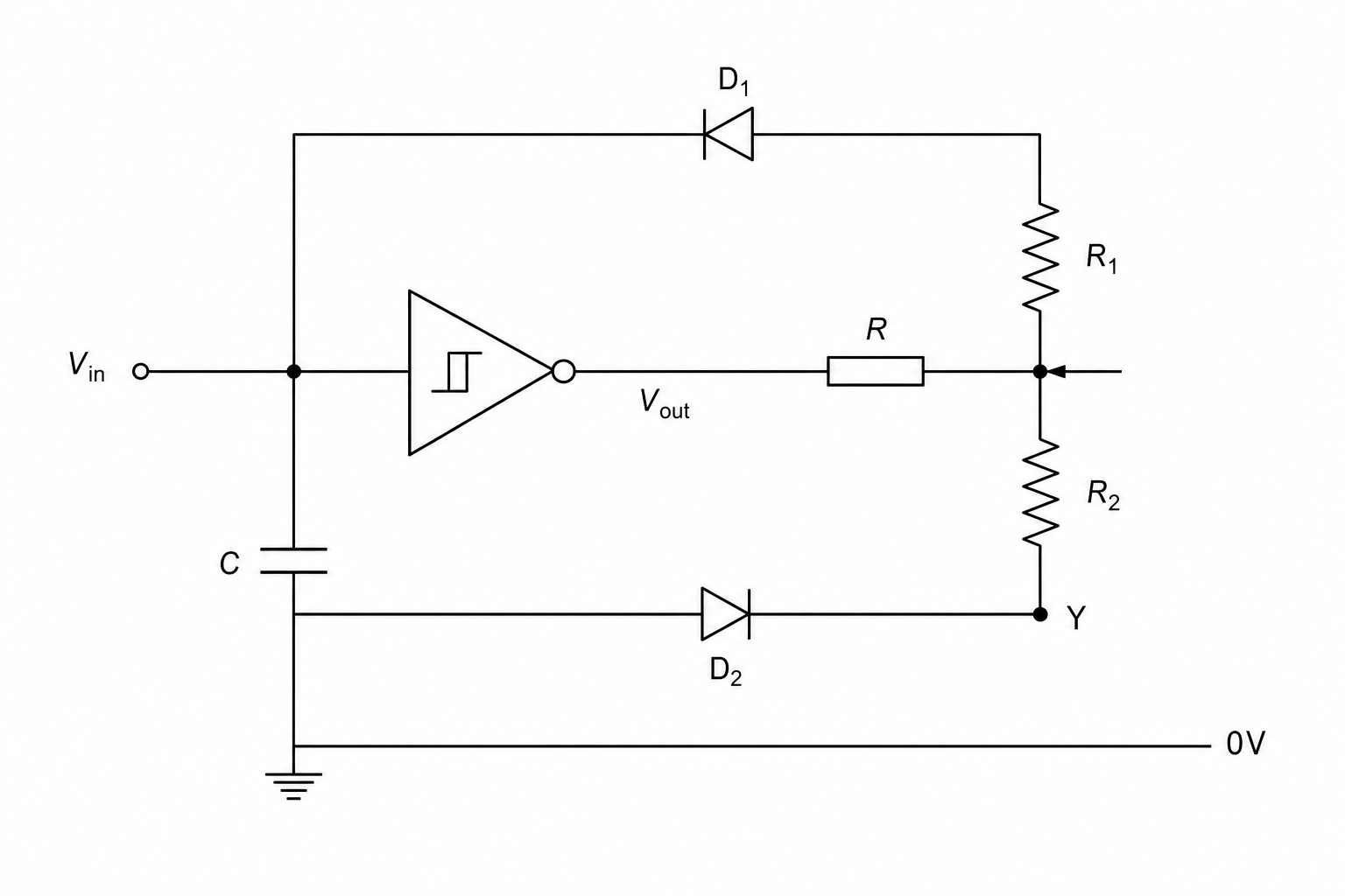
Figure 2 shows the oscillator circuit after it has been modified by the addition of:
- two diodes D1D_1D1 and D2D_2D2
- a potential divider (potentiometer) that has a total resistance value of (R1+R2)(R_1 + R_2)(R1+R2)
In this particular circuit:
- the time tHt_HtH for the output signal to be HIGH is given by tH=0.8C(R+R1)t_H = 0.8C(R + R_1)tH=0.8C(R+R1)
- the time tLt_LtL for the output signal to be LOW is given by tL=0.8C(R+R2)t_L = 0.8C(R + R_2)tL=0.8C(R+R2)
The slider of the potentiometer is moved towards terminal YYY (at the bottom, near diode D2D_2D2), as shown in Figure 2.
State and explain the effect of this change on:
- the mark-to-space ratio (tH:tLt_H : t_LtH:tL)
- the pulse repetition frequency (PRF).