What you'll learn
- How charge, voltage, and current change over time as a capacitor charges and discharges.
- What the time constant (RCRCRC) is and how to calculate it.
- How to use exponential equations to find circuit values at any given time.
- How to linearise capacitor discharge data using log-linear graphs (Required Practical 9).
The charging and discharging circuit
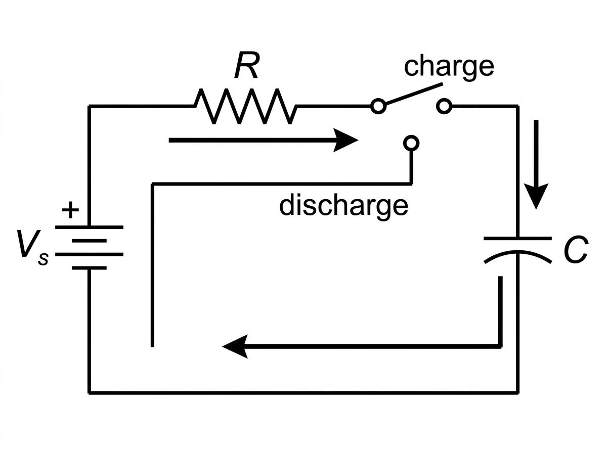
When a capacitor is connected directly to a battery, it charges almost instantly. In practice, circuits have resistance. By deliberately placing a resistor in series with a capacitor, we can slow down the rate at which electrons flow onto or off the capacitor plates. This allows us to measure and model the charging and discharging process over time.
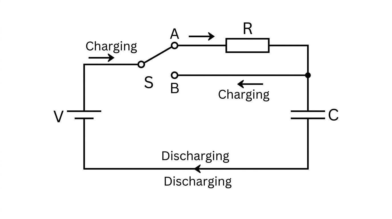
In a typical setup, a two-way switch allows the capacitor to either connect to a power supply (to charge) or to loop back on itself through a resistor (to discharge).
Discharging a capacitor
Imagine a capacitor that is already fully charged to an initial voltage V0V_0V0, holding an initial charge Q0Q_0Q0. When the switch is flipped to discharge, the electrons on the negative plate repel each other and rush through the external circuit (and the resistor) to reach the positive plate.
As electrons leave the negative plate, the total charge QQQ left on the capacitor decreases. Because V=QCV = \frac{Q}{C}V=CQ, the potential difference VVV across the capacitor also decreases. A smaller potential difference means there is a weaker "push" driving the electrons, so the current III (the rate of flow of charge) also decreases.
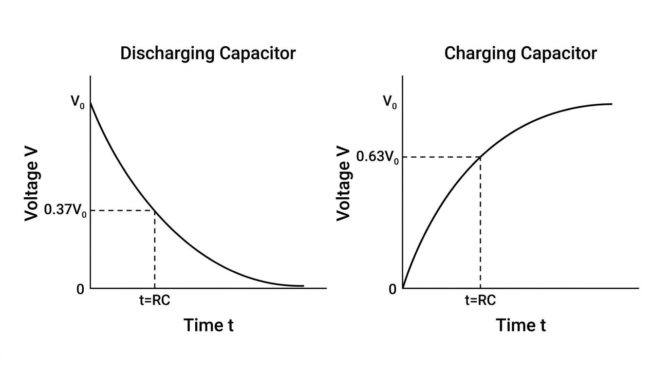
Because the rate at which the charge drops is directly proportional to the amount of charge remaining, the process is an exponential decay. If you plot charge, voltage, or current against time for a discharging capacitor, all three graphs show the exact same shape: a curve starting at a maximum value and decaying towards zero.
Time constant ()
The time constant of a capacitor-resistor circuit is the time taken for the charge, voltage, or current of a discharging capacitor to fall to 1/e1/e1/e (approximately 37%) of its initial value. It is found by multiplying the resistance by the capacitance.
The time constant is given the symbol τ\tauτ (tau), but is most often just written as RCRCRC:
τ=RC \tau = RC τ=RCwhere RRR is resistance in ohms (Ω\OmegaΩ) and CCC is capacitance in farads (F\text{F}F). The resulting time constant is measured in seconds (s\text{s}s).
The 37% and 63% rules
A quick way to check your working or sketch a graph: after exactly one time constant (t=RCt = RCt=RC), a discharging value drops to approximately 37% of its start value (because e−1≈0.37e^{-1} \approx 0.37e−1≈0.37). A charging value rises to approximately 63% of its maximum value (because 1−e−1≈0.631 - e^{-1} \approx 0.631−e−1≈0.63).
Time to halve (Half-life)
Just like radioactive decay, capacitor discharge has a half-life. The time to halve, T1/2T_{1/2}T1/2, is the time taken for the charge, voltage, or current to fall to exactly half of its initial value.
By setting V=0.5V0V = 0.5 V_0V=0.5V0 in the discharge equations and solving for time, you get a highly useful shortcut formula explicitly listed on your AQA data sheet:
T1/2=0.69RCT_{1/2} = 0.69RCT1/2=0.69RCThe discharging equations
We can treat the exponential decay quantitatively using equations. For a discharging capacitor, charge QQQ, voltage VVV, and current III all follow the standard exponential decay formula:
Q=Q0e−tRC Q = Q_0 e^{-\frac{t}{RC}} Q=Q0e−RCt V=V0e−tRC V = V_0 e^{-\frac{t}{RC}} V=V0e−RCt I=I0e−tRC I = I_0 e^{-\frac{t}{RC}} I=I0e−RCtWhere ttt is the elapsed time in seconds, and the subscript "000" indicates the initial maximum value at t=0t = 0t=0.
Calculating discharge time
A capacitor of capacitance C=470μFC = 470 \mu\text{F}C=470μF is charged to an initial voltage V0=12 VV_0 = 12 \text{ V}V0=12 V and then discharged through a resistor of resistance R=50 kΩR = 50 \text{ k}\OmegaR=50 kΩ. Calculate the time taken for the voltage across the capacitor to fall to 3.0 V3.0 \text{ V}3.0 V.
- Find the time constant. Calculate the product of resistance and capacitance, making sure to use standard units (Ω\OmegaΩ and F\text{F}F).
- State the decay equation. Because the capacitor is discharging, the voltage is falling exponentially.
- Rearrange for time ttt. Divide both sides by V0V_0V0, then take the natural logarithm (ln\lnln) of both sides to remove the exponential.
- Substitute your values and evaluate.
Charging a capacitor
When an uncharged capacitor is connected to a DC supply voltage, electrons are pushed onto the negative plate and pulled off the positive plate. As the charge builds up, the capacitor's own potential difference pushes back against the supply voltage.
Because the "net" voltage driving the current (Supply Voltage −-− Capacitor Voltage) gets smaller over time, the rate at which the capacitor charges slows down.
- Charge (QQQ) and Voltage (VVV) both start at zero and rise exponentially, eventually levelling off at a maximum value.
- Current (III) starts at its maximum initial value (I0=VsupplyRI_0 = \frac{V_{\text{supply}}}{R}I0=RVsupply) and decays exponentially to zero as the capacitor becomes full.
Using the wrong equation for charging current
Students often assume that because a capacitor is charging, its current must be increasing. Remember that as a capacitor charges, it increasingly resists further flow of charge, meaning the current starts at a maximum and decays to zero. Current always uses the e−t/RCe^{-t/RC}e−t/RC decay equation, whether charging or discharging!
The charging equations
Because charge and voltage are rising to a maximum rather than falling to zero, they use an exponential growth equation:
Q=Q0(1−e−tRC) Q = Q_0 \left( 1 - e^{-\frac{t}{RC}} \right) Q=Q0(1−e−RCt) V=V0(1−e−tRC) V = V_0 \left( 1 - e^{-\frac{t}{RC}} \right) V=V0(1−e−RCt)Calculating charge during charging
An uncharged capacitor of capacitance C=1000μFC = 1000 \mu\text{F}C=1000μF is connected in series with a resistor of resistance R=2.0 MΩR = 2.0 \text{ M}\OmegaR=2.0 MΩ and a 5.0 V battery. Calculate the charge on the capacitor after 3.0 s of charging.
- Calculate the time constant RCRCRC.
- Calculate the maximum possible charge Q0Q_0Q0. This is the charge when the capacitor reaches the full 5.0 V of the supply.
- State the charging equation. Because the charge is rising from zero to a maximum, we use the growth equation.
- Substitute your values and evaluate.
Interpreting capacitor graphs
When you look at graphical representations of capacitor circuits, the geometry of the curves holds valuable physics information:
- Gradient of a QQQ against ttt graph: Because current is the rate of flow of charge (I=ΔQΔtI = \frac{\Delta Q}{\Delta t}I=ΔtΔQ), the gradient of a tangent to a charge-time graph at any given time yields the instantaneous current.
- Area under an III against ttt graph: Because total charge is current multiplied by time (ΔQ=IΔt\Delta Q = I \Delta tΔQ=IΔt), the area bounded by a current-time curve and the time axis represents the total charge transferred over that period.
Required Practical 9: Log-linear graphs
In the lab, you investigate capacitor discharge by recording the voltage across a capacitor at regular time intervals. Plotting VVV against ttt directly gives a curve, which is notoriously difficult to analyse accurately or use to find a precise value for RCRCRC. Instead, we use log-linear plotting to map the exponential decay curve into a straight line.
Start with the standard discharge equation:
V=V0e−tRCV = V_0 e^{-\frac{t}{RC}}V=V0e−RCtTake the natural logarithm (ln\lnln) of both sides:
ln(V)=ln(V0e−tRC)ln(V)=ln(V0)−tRC\begin{aligned} \ln(V) &= \ln \left( V_0 e^{-\frac{t}{RC}} \right) \\ \ln(V) &= \ln(V_0) - \frac{t}{RC} \end{aligned}ln(V)ln(V)=ln(V0e−RCt)=ln(V0)−RCtWe can map this exactly to the equation of a straight line, y=mx+cy = mx + cy=mx+c:
ln(V)=(−1RC)t+ln(V0)y=mx+c\begin{aligned} \ln(V) &= \left( -\frac{1}{RC} \right) t + \ln(V_0) \\ y &= m x + c \end{aligned}ln(V)y=(−RC1)t+ln(V0)=mx+cBy plotting a graph with ln(V)\ln(V)ln(V) on the y-axis against ttt on the x-axis:
- The graph will be a straight line with a negative gradient.
- The gradient mmm is equal to −1RC-\frac{1}{RC}−RC1.
- The y-intercept is ln(V0)\ln(V_0)ln(V0).
Once you calculate the gradient from your line of best fit, you can find the time constant accurately:
RC=−1gradientRC = -\frac{1}{\text{gradient}}RC=−gradient1In the exam
- Always double-check the prefix multipliers. Capacitance is almost always given in microfarads (μF\mu\text{F}μF, 10−610^{-6}10−6) or picofarads (pF\text{pF}pF, 10−1210^{-12}10−12), while resistance is often in kilohms (kΩ\text{k}\OmegakΩ, 10310^3103) or megohms (MΩ\text{M}\OmegaMΩ, 10610^6106). Forgetting to convert these before finding RCRCRC will ruin your calculation.
- Read the question carefully to pick the correct equation. A value "falling from" an initial maximum requires the e−tRCe^{-\frac{t}{RC}}e−RCt equation. A value "rising to" a maximum requires the (1−e−tRC)(1 - e^{-\frac{t}{RC}})(1−e−RCt) equation.
- Remember that eee and ln\lnln are inverses. If you need to bring time ttt down from an exponent, you must isolate the eee term completely on one side of the equation before taking the natural log (ln\lnln) of both sides.
- Current graphs never start at zero. For both charging and discharging, the current graph starts at a maximum initial value (I0=V0RI_0 = \frac{V_0}{R}I0=RV0) and drops exponentially.
Check yourself
- What physical quantity is found by taking the area under a current-time graph?
- If a capacitor circuit has a time constant of 10 seconds, roughly what percentage of its original voltage will remain after 10 seconds of discharging?
- Why do you use the e−tRCe^{-\frac{t}{RC}}e−RCt decay equation for current, even when the capacitor is actively charging?
- When performing a log-linear plot for a discharging capacitor (ln(V)\ln(V)ln(V) against ttt), what does the gradient of the resulting straight line represent?