Astronomical telescope consisting of two converging lenses (A-level only)
You have probably looked through a telescope or binoculars before, but how exactly do they make distant stars and planets look closer? In this topic, we will break down the optics of a simple refracting telescope.
What you'll learn:
- The roles of the objective and eyepiece lenses.
- How to draw a precise ray diagram for a telescope in "normal adjustment".
- Why we use "angular magnification" instead of linear magnification for astronomy.
- How to calculate the magnifying power of a telescope using focal lengths and subtended angles.
The Anatomy of a Refracting Telescope
A simple refracting astronomical telescope is built using two converging lenses (convex lenses that focus parallel rays of light to a point).
- The Objective Lens: This is the large lens at the front of the telescope. Its job is to collect as much light as possible from a distant object and bring it to a focus to form a real image inside the telescope tube. It has a relatively long focal length, fof_ofo.
- The Eyepiece Lens: This is the smaller lens you look through. It acts like a magnifying glass, taking the real image formed by the objective lens and magnifying it so your eye can see its details. It has a relatively short focal length, fef_efe.
Focal Length
The focal length is the distance from the centre of a lens to its principal focus (the point where parallel rays of light converge). We use fof_ofo for the objective lens and fef_efe for the eyepiece lens.
Normal Adjustment
When astronomers look at the night sky, they are looking at objects that are incredibly far away. Because the objects are at "infinity", the rays of light from any single point on a star arrive at the telescope completely parallel to each other.
If you set up a telescope so that the light rays leaving the eyepiece and entering your eye are also parallel, the telescope is said to be in normal adjustment.
Why use normal adjustment?
If the light rays entering your eye are parallel, your eye's lens does not have to actively focus (accommodate) to see the image. The image appears to be at infinity. This prevents eye strain during long nights of stargazing!
For the emergent rays to be parallel, the intermediate image created by the objective lens must fall exactly on the principal focus of the eyepiece lens.
Because the intermediate image is also formed at the principal focus of the objective lens, the two focal points must perfectly overlap. This tells us a crucial fact about the physical length of the telescope:
The distance between the two lenses must be exactly the sum of their focal lengths: fo+fef_o + f_efo+fe.
Calculating telescope length
A student is building a simple astronomical telescope in normal adjustment. They are using an objective lens with a focal length of 850 mm850 \text{ mm}850 mm and an eyepiece lens with a focal length of 25 mm25 \text{ mm}25 mm. Calculate the required distance between the two lenses in metres.
- Recall that for normal adjustment, the principal focus of the objective lens must coincide with the principal focus of the eyepiece lens.
- State the formula for the separation of the lenses: Separation=fo+fe\text{Separation} = f_o + f_eSeparation=fo+fe.
- Convert the given values into SI units (metres): fo=0.850 mf_o = 0.850 \text{ m}fo=0.850 m and fe=0.025 mf_e = 0.025 \text{ m}fe=0.025 m.
- Add the focal lengths together: 0.850+0.025=0.875 m0.850 + 0.025 = 0.875 \text{ m}0.850+0.025=0.875 m.
Drawing the Ray Diagram
Drawing the ray diagram for a telescope in normal adjustment is a very common AQA exam question. You must draw it accurately to get all the marks.
Look at the diagram below, and then read the steps on how to construct it.
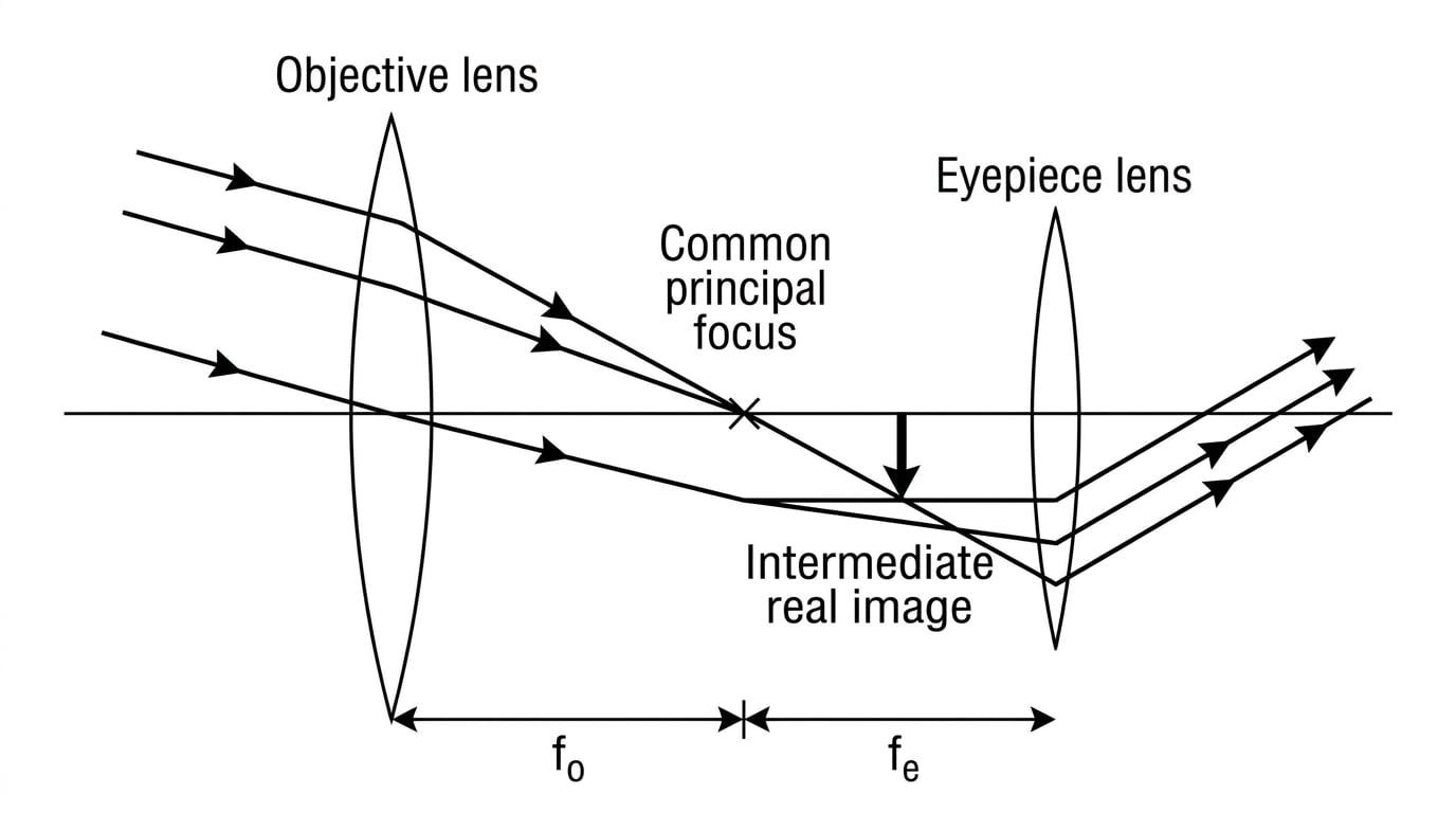
Here is the exact method to construct this diagram from scratch:
- Draw a horizontal principal axis and add two vertical lines to represent the objective and eyepiece lenses. Place a common focal point between them, much closer to the eyepiece.
- Draw a straight, diagonal line right through the optical centre (the middle) of the objective lens. It should pass through untouched. This represents the central ray from the top of the distant object.
- Draw two more rays parallel to this first one, entering the objective lens from the top and bottom.
- Continue all three rays so they converge and meet at the same point on the focal plane (a vertical line dropped down from the common focal point).
- Draw a dashed "construction line" from this meeting point straight through the optical centre of the eyepiece lens.
- Continue your three actual solid light rays from the intermediate image to the eyepiece lens.
- From the eyepiece lens, bend all three solid rays so they emerge perfectly parallel to your dashed construction line.
Failing to draw parallel rays
A guaranteed way to lose marks in a drawing question is having the final rays exiting the eyepiece converge or diverge. Because the telescope is in normal adjustment, those three final rays must be perfectly parallel to each other!
Angular Magnification
When dealing with a normal magnifying glass, we often talk about linear magnification (how many times taller the image is compared to the object). However, stars are so far away that their actual physical size is meaningless to our unaided eye, and they look like infinitely small dots.
Instead of linear size, astronomers care about the angle an object takes up in your field of view.
Angular Magnification
The angular magnification, MMM, of a telescope is defined as:
M=angle subtended by image at eyeangle subtended by object at unaided eye M = \frac{\text{angle subtended by image at eye}}{\text{angle subtended by object at unaided eye}} M=angle subtended by object at unaided eyeangle subtended by image at eyeYou will often see the angle subtended by the image called β\betaβ and the angle subtended by the object called α\alphaα. Therefore, you can write the equation as:
M=βα M = \frac{\beta}{\alpha} M=αβNotice that MMM is a ratio of two angles, meaning it has no units.
By using small-angle approximations on the geometry of the ray diagram, we can relate this ratio of angles directly to the focal lengths of the two lenses. This gives us the second crucial equation for your A-level specification:
M=fofe M = \frac{f_o}{f_e} M=fefoThis beautifully simple equation tells you that to get the highest possible magnification, you want an objective lens with a very long focal length, and an eyepiece lens with a very short focal length.
Calculating angular magnification
An astronomical telescope is used in normal adjustment to view a distant crater on the Moon. The focal length of the objective lens is 1.20 m1.20 \text{ m}1.20 m and the focal length of the eyepiece lens is 40 mm40 \text{ mm}40 mm. The crater subtends an angle of 2.5×10⁻⁴ rad2.5 \times 10^{-4} \text{ rad}2.5×10⁻⁴ rad to the unaided eye. Calculate the angle subtended by the image of the crater when looking through the telescope.
- Convert all lengths to the same units. Let's use metres: fo=1.20 mf_o = 1.20 \text{ m}fo=1.20 m and fe=0.040 mf_e = 0.040 \text{ m}fe=0.040 m.
- Calculate the angular magnification of the telescope using the focal lengths:
- State the definition of angular magnification in terms of angles:
- Rearrange the formula to solve for the angle subtended by the image:
- Substitute the known values to find the final answer:
Angles in Radians
In astrophysics calculations, subtended angles are incredibly small. Get comfortable working with radians in standard form (e.g., 1.5×10⁻³ rad1.5 \times 10^{-3} \text{ rad}1.5×10⁻³ rad). There is rarely any need to convert to degrees!
In the exam
- When asked to draw the ray diagram, always use a ruler and a sharp pencil. Freehand sketches will lose marks for accuracy.
- Check that your central incoming ray goes straight through the centre of the objective lens without bending.
- Ensure the intermediate image forms exactly at the shared focal point of both lenses. You can indicate this by adding a small label fof_ofo and fef_efe along the principal axis.
- Remember that the final bundle of rays leaving the eyepiece must be steeper than the bundle of rays that entered the objective. This visualises the magnification!
- Never add units to angular magnification (MMM). If a question asks for MMM, it is just a number.
Check yourself
- What does the term "normal adjustment" mean for the final light rays leaving the telescope?
- If a telescope has an objective focal length of 2.0 m2.0 \text{ m}2.0 m and an eyepiece focal length of 0.05 m0.05 \text{ m}0.05 m, what is the distance between the lenses in normal adjustment?
- Why is it more useful to describe a telescope's power using angular magnification rather than linear magnification?