A generator turns a coil in a magnetic field to induce an e.m.f.
- A simple a.c. generator is a rectangular coil mounted on an axle between the poles of a magnet.
- Turning the coil makes its sides cut across the magnetic field lines, which induces an e.m.f. in the coil.
- At any instant the two long sides are moving in opposite directions, so their e.m.f.s add together as you go round the loop rather than cancelling.
- Half a turn later each side is moving the opposite way, so the induced e.m.f. has reversed, and that is what makes the output alternating.
- The alternative design keeps the coil fixed and rotates the magnet instead, producing the same changing field through the coil with no moving electrical connections.
- Power stations use the rotating-magnet design, because it avoids carrying an enormous current through sliding contacts.
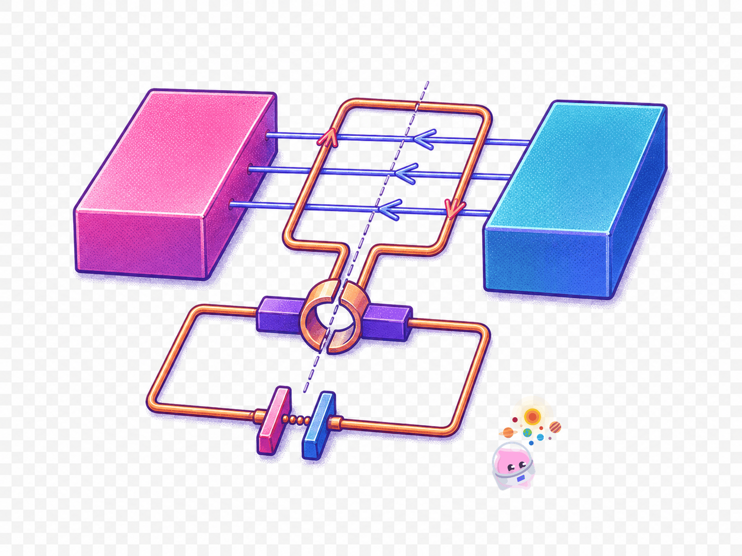
Slip rings and brushes carry the current out of a spinning coil
- A rotating coil cannot be wired straight into a circuit, because the leads would twist round the axle and snap within a few turns.
- Each end of the coil is therefore joined to its own slip ring, a complete metal ring that turns with the axle.
- A carbon brush presses against each ring, keeping contact while the ring turns underneath it.
- Because each slip ring stays connected to the same end of the coil all the way round, the output keeps reversing exactly as the coil does.
- That is the difference from a motor's split-ring commutator, which swaps the connections every half turn and so produces a one-way output instead.
- A rotating-magnet generator needs no slip rings at all, because its coil never moves.
Reading the e.m.f.-time graph off the coil's position
- The output is a smooth wave that rises to a peak, falls through zero to a trough, and returns, giving one full cycle per revolution.
- The e.m.f. is at a peak when the coil lies in the plane of the field lines, because its sides are then cutting straight across the field at the greatest rate.
- The e.m.f. is zero when the coil is at right angles to the field, because its sides are then moving along the field lines instead of cutting them.
- Between those two positions the e.m.f. takes intermediate values, which is what gives the curve its smooth shape.
- Each half turn produces one peak or one trough, so a complete revolution gives one whole cycle of output.
- Turning the coil faster raises the peaks and squashes the cycles together, so both the e.m.f. and the frequency increase.
- Using a stronger magnet or more turns raises the peaks without changing the frequency at all.
Common Mistake
- The e.m.f. peaks when the coil is in the plane of the field, cutting the lines fastest, so do not pair the peak with the position at right angles to the field.
- A generator uses slip rings, never a split-ring commutator, which belongs to the d.c. motor.
- Spinning the coil faster changes the frequency as well as the peak e.m.f., so a sketch showing only taller peaks is incomplete.
- A generator does not create charge or electrons; it induces an e.m.f. that drives the charge already in the circuit.
Exam technique
- When a graph question marks a point on the curve, answer with the coil position and the reason, not just "the e.m.f. is maximum here".
- Label both axes on a sketch, mark one complete cycle, and draw the curve crossing the time axis twice per revolution.
- If asked to show the effect of doubling the speed, draw the new curve on the same axes with taller peaks and half the period.
- Name the parts precisely in a description: coil, magnet, axle, slip rings and brushes.
Self review
- Describe the construction of a simple a.c. generator.
- What is the job of the slip rings and brushes?
- At which coil position is the induced e.m.f. greatest, and why?
- At which coil position is the e.m.f. zero, and why?
- Sketch how the e.m.f.-time graph changes when the coil is turned twice as fast.
