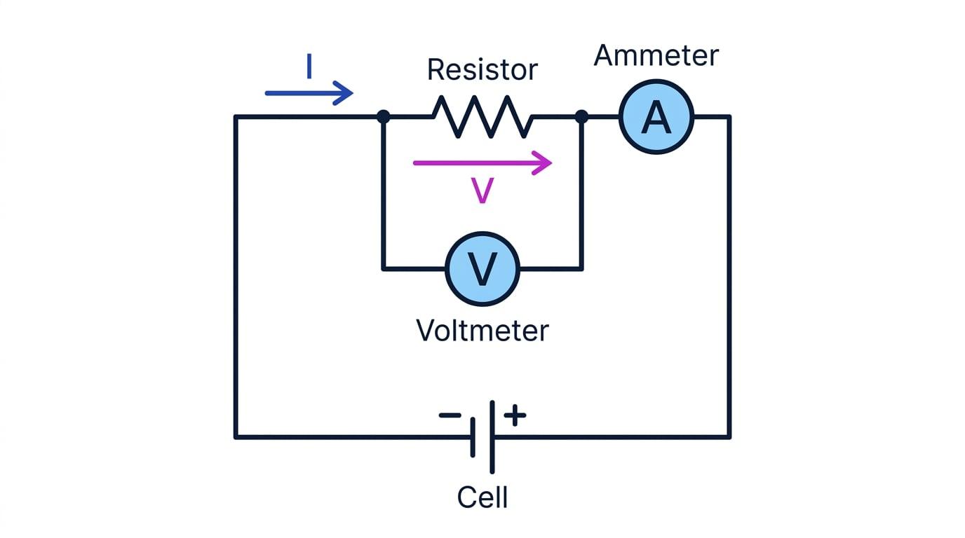
At a fixed current, more resistance means a bigger p.d.
- From V=IRV = IRV=IR, holding the current constant makes the p.d. across a component proportional to its resistance.
- So doubling the resistance at the same current doubles the p.d. across that component.
- In a series circuit the current is the same everywhere, which is exactly the constant-current condition this rule needs.
- The component with the largest resistance therefore takes the largest share of the supply p.d.
- That is why a thin, high-resistance element in a heater glows red while the thick leads carrying the same current stay cool.
A potential divider taps off part of the supply voltage
Definition
Potential divider
Two resistors in series across a supply, arranged so that the p.d. across one of them can be used as a smaller output voltage.
R1R2=V1V2 \frac{R_1}{R_2} = \frac{V_1}{V_2} R2R1=V2V1- Two resistors in series share the supply p.d. between them, so taking the output across just one of them gives a fraction of the supply.
- The share each one takes is fixed by the ratio of the resistances, because the same current passes through both.
- The larger resistance always takes the larger p.d., so two equal resistors split the supply exactly in half.
- A variable potential divider replaces the two fixed resistors with one length of resistance wire and a sliding contact.
- Sliding the contact changes both lengths at once, raising one share while it lowers the other, so the output can be set anywhere from zero up to the full supply.
- That is what the volume control on a speaker does, varying how much of the input signal is passed on to the amplifier.
Practical
Investigation: how a potential divider splits a voltage
- Aim: to investigate how a potential divider shares the supply voltage between two resistors, and how putting a thermistor in one position changes the output.
- Apparatus: a d.c. supply, a fixed resistor, a variable resistor, a thermistor, two voltmeters, an ammeter, a switch, a beaker of warm water and connecting leads.
- Method:
- Connect the fixed resistor and the variable resistor in series across the d.c. supply, with the switch and the ammeter in the same loop.
- Connect one voltmeter across the fixed resistor and the second voltmeter across the variable resistor.
- Close the switch, let the readings settle, and record the current and both voltages together.
- Move the slider on the variable resistor to a new setting and record a second set, then a third and a fourth.
- Work out V1/V2V_1/V_2V1/V2 and R1/R2R_1/R_2R1/R2 for each set and compare the two ratios.
- Replace the variable resistor with the thermistor, then warm it in the beaker of water and let it cool again, recording how both voltages change.
- Measure and record: tabulate the readings under I / A, V₁ / V and V₂ / V, with extra columns for V1/V2V_1/V_2V1/V2 and R1/R2R_1/R_2R1/R2; no graph is required.
- Result: the supply p.d. divides in the ratio of the resistances, so V1V2=R1R2\dfrac{V_1}{V_2} = \dfrac{R_1}{R_2}V2V1=R2R1; warming the thermistor lowers its resistance, which lowers the p.d. across it and raises the p.d. across the other resistor.
- Watch out:
- Let the thermistor settle at each temperature before reading, because its resistance keeps drifting while it is still warming or cooling.
- Read both voltmeters at the same moment, since changing the slider changes the current and both readings at once.
- Switch off between changes so that the resistors do not warm up and drift during the experiment.
- Check that the two voltages add up to the supply voltage at every setting, as a running test on the readings.
- Safety: keep the circuit and the leads well away from the beaker of water, and switch off before changing any component.
Sensing circuits swap one resistor for a component that responds
- Replacing one of the two resistors with a thermistor turns the divider into a temperature sensor.
- As the thermistor warms its resistance falls, so it takes a smaller share of the supply and the p.d. across the other resistor rises.
- Using an LDR instead does the same job for light, since its resistance falls when it is brightly lit.
- Feeding that changing output into a switching circuit is how a thermostat, a frost alarm and a dusk-to-dawn street light all work.
- Swapping which of the two components the output is taken across reverses the behaviour, so the same parts can give a rising or a falling output.
Common Mistake
- The larger resistance takes the larger p.d., so check which resistor the output is taken across before you answer.
- R1R2=V1V2\dfrac{R_1}{R_2} = \dfrac{V_1}{V_2}R2R1=V2V1 only holds when the same current passes through both, so the two resistors must be in series.
- A thermistor's resistance falls as it gets hotter, so the p.d. across it falls as well.
- Keep the units consistent: a ratio taken in kΩ\text{k}\OmegakΩ equals the ratio in Ω\OmegaΩ, but do not put one of each into the same line.
Exam technique
- Say which resistor the output is taken across in the first line of your answer, because everything after that depends on it.
- Thinking in shares is quicker than the formula: a 3:13 : 13:1 resistance ratio means four shares of the supply.
- For a sensing question, trace the chain out loud: the temperature or light changes, then the resistance, then the share of the p.d., then the output.
- Check your two p.d.s add to the supply before you write the final line.
Self review
- At a constant current, how does the p.d. across a conductor change as its resistance increases?
- Describe the action of a variable potential divider.
- State the equation linking the two resistances and the two p.d.s in a potential divider.
- A 10 V10\ \text{V}10 V supply is across a 2.0 kΩ2.0\ \text{k}\Omega2.0 kΩ and a 8.0 kΩ8.0\ \text{k}\Omega8.0 kΩ resistor in series. Find the p.d. across the smaller resistor.
- A thermistor forms one half of a potential divider. Explain what happens to the p.d. across it as the room warms up.