Revision notes for OCR GCSE Physics Uses of magnetism. Open the guide for explanations and worked examples. Written against the OCR GCSE Physics (J249) specification, so the content matches what's examinable rather than general Physics background.
Uses of magnetism
What you'll learn
- How a current-carrying wire can experience a force in a magnetic field.
- How Fleming’s left-hand rule links current, magnetic field and force.
- How motors, generators, transformers, microphones and loudspeakers use magnetism.
- How to calculate magnetic forces and transformer potential differences.
A quick spec note: this P4.2 material is shown as Higher Tier only in your OCR extract. From electromagnetic induction onwards, it is also separate Physics J249 only, not Combined Science.
The starting point: fields, currents and conductors
A conductor is a material that allows charge to flow through it easily. Metals such as copper are good conductors, which is why copper wire is used in circuits.
An electric current is a flow of charge, measured in amperes (A).
Definition
Magnetic field
A magnetic field is the region around a magnet, current-carrying wire or electromagnet where another magnetic material or moving charge can experience a force.
Magnetic field lines show the direction of the field. Around a bar magnet, they go from the north pole to the south pole outside the magnet.
The motor effect
When a current-carrying conductor is placed in a magnetic field, the conductor and the magnet exert forces on each other. This is because the magnetic field around the current interacts with the magnetic field from the magnet.
Definition
Motor effect
The motor effect is the force on a current-carrying conductor placed in a magnetic field.
The force is strongest when the conductor is at right angles to the magnetic field. If the wire is free to move, it may “jump” in a classroom demonstration.
Key Idea
Three directions at right angles
For the motor effect, the force, magnetic field and current are all at right angles to each other. Reversing the current or reversing the magnetic field reverses the force.
Fleming’s left-hand rule
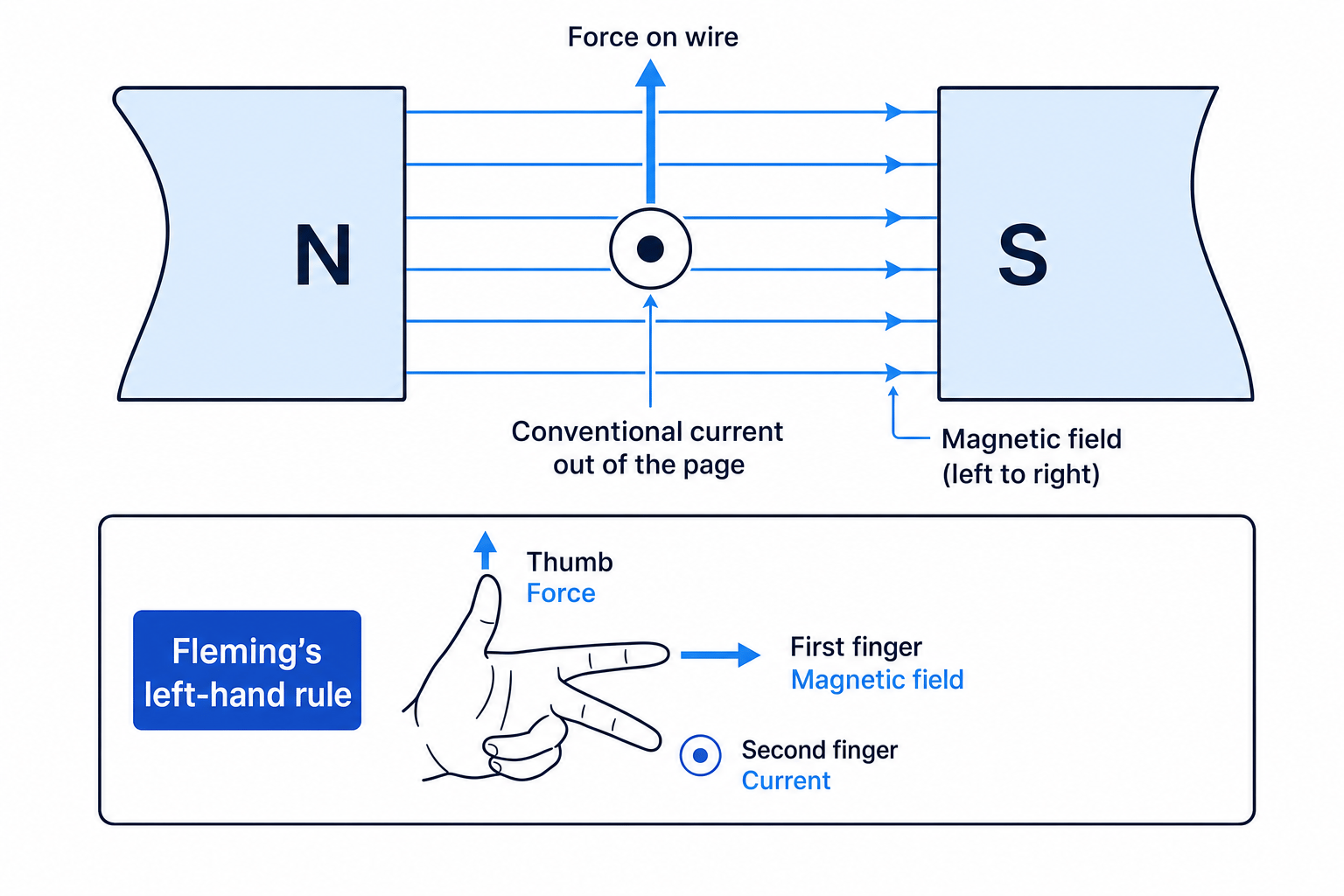
Fleming’s left-hand rule helps you predict the direction of the force.
Hold your left hand with thumb, first finger and second finger all at right angles:
- Thumb = force or motion
- First finger = magnetic field, from north to south
- Second finger = conventional current
Conventional current is the direction positive charge would move, from the positive terminal to the negative terminal. It is opposite to electron flow.
Example
Finding the force direction
A wire carries conventional current out of the page in a magnetic field from left to right.
- Point your first finger from left to right, because the magnetic field goes from north to south.
- Point your second finger out of the page, because that is the direction of conventional current.
- Your thumb points upwards, so the force on the wire is upwards.
Common Mistake
Using electron flow instead of conventional current
In Fleming’s left-hand rule, always use conventional current, not electron flow. If you use electron flow, your force direction will be reversed.
Calculating the force on a conductor
The magnetic force on a straight conductor at right angles to a magnetic field is:
F=BIlF = B I lF=BIlwhere:
- FFF is force in newtons (N)
- BBB is magnetic flux density in tesla (T)
- III is current in amperes (A)
- lll is the length of conductor inside the magnetic field in metres (m)
Definition
Magnetic flux density
Magnetic flux density, BBB, is a measure of the strength of a magnetic field. It is measured in tesla (T).
For OCR Gateway, this is an apply equation rather than a recall equation, so you should be given it. You still need to know when it applies and how to rearrange it.
Common Mistake
Only use the equation for right angles
The equation F=BIlF = BIlF=BIl is for a conductor at right angles to the magnetic field. Also use only the length of wire actually inside the magnetic field.
Example
Calculating the force on a wire
A wire of length 8.0 cm is at right angles to a magnetic field of flux density 0.25 T. The current is 4.0 A. Calculate the force.
-
Convert the length into metres: 8.0 cm = 0.080 m.
-
Substitute into F=BIlF = BIlF=BIl:
F=0.25 T×4.0 A×0.080 mF = 0.25\ \text{T} \times 4.0\ \text{A} \times 0.080\ \text{m}F=0.25 T×4.0 A×0.080 m -
Calculate the force:
F=0.080 NF = 0.080\ \text{N}F=0.080 N
How electric motors use the motor effect
An electric motor uses the motor effect to produce rotation.
In a simple motor, a coil of wire sits in a magnetic field. Current flows one way on one side of the coil and the opposite way on the other side. So the two sides experience forces in opposite directions: one side is pushed up, the other is pushed down.
This creates a turning effect, meaning the coil rotates about an axis.
In a d.c. motor, the current must be reversed every half-turn so the coil continues rotating in the same direction. A commutator is the switching part that can reverse the connections. You do not need detailed motor construction for this spec point, but you do need the idea that opposite forces cause rotation.
Example
Explaining why a coil turns
A coil is between a north pole and a south pole, so the magnetic field is left to right. On the left side of the coil, current is out of the page. On the right side, current is into the page.
- Apply Fleming’s left-hand rule to the left side: field left to right and current out of the page gives an upward force.
- Apply it to the right side: field left to right and current into the page gives a downward force.
- The upward and downward forces act on opposite sides of the coil, producing a turning effect, so the coil rotates.
Electromagnetic induction
From this point, the ideas are separate Physics J249 content.
Definition
Electromagnetic induction
Electromagnetic induction is when a changing magnetic field around a conductor induces a potential difference across the conductor.
A potential difference is the energy transferred per unit charge, measured in volts (V). If the conductor is part of a complete circuit, the induced potential difference can drive an induced current.
The induced current produces its own magnetic field. This field acts to oppose the original change that caused it.
Key Idea
No change, no induction
A steady magnetic field does not keep inducing a potential difference. You need a changing magnetic field: for example, a moving magnet, a moving coil, or an alternating current.
Example
Predicting induction in a coil
A north pole of a magnet is pushed into a coil connected to a sensitive meter.
- As the magnet moves into the coil, the magnetic field through the coil changes, so a potential difference is induced.
- Because the circuit is complete, an induced current flows and the meter deflects.
- The induced current creates a magnetic field that opposes the change, so the coil’s near end acts like a north pole to resist the approaching north pole.
Alternators and dynamos
An alternating current (a.c.) repeatedly changes direction. A direct current (d.c.) flows in one direction only.
An alternator generates a.c. by rotating a coil, or rotating a magnet, so the magnetic field through the coil keeps changing. The induced potential difference reverses every half-turn, so the output is alternating.
A dynamo generates d.c. using the same induction effect, but with switching connections so the output current in the external circuit stays in one direction.
Example
Choosing the generator output
A rotating coil generator has a changing magnetic field through the coil.
- The changing magnetic field induces a potential difference across the coil.
- If the connections allow the polarity to reverse every half-turn, the output is a.c., so the device acts as an alternator.
- If a commutator reverses the connections every half-turn, the external current stays in one direction, so the output is d.c., like a dynamo.
Transformers
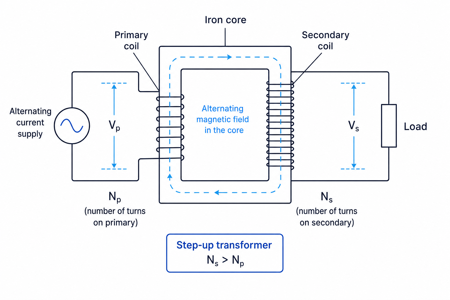
A transformer changes the size of an alternating potential difference. It has a primary coil connected to the input and a secondary coil connected to the output. The coils are wrapped around an iron core.
An alternating current in the primary coil creates a changing magnetic field in the iron core. This changing field passes through the secondary coil and induces a potential difference across it.
Common Mistake
Trying to use steady d.c. in a transformer
A transformer needs a changing magnetic field, so it works with a.c. A steady d.c. supply does not keep inducing a potential difference in the secondary coil.
For a transformer:
VpVs=NpNs\frac{V_p}{V_s} = \frac{N_p}{N_s}VsVp=NsNpwhere:
- VpV_pVp is the potential difference across the primary coil
- VsV_sVs is the potential difference across the secondary coil
- NpN_pNp is the number of turns on the primary coil
- NsN_sNs is the number of turns on the secondary coil
This transformer ratio is also an apply equation for OCR, so it should be given. You need to use it confidently.
If NsN_sNs is greater than NpN_pNp, the transformer is step-up and increases potential difference. If NsN_sNs is less than NpN_pNp, it is step-down and decreases potential difference.
Example
Calculating transformer output potential difference
A transformer has 1200 turns on the primary coil and 100 turns on the secondary coil. The primary potential difference is 230 V. Calculate the secondary potential difference.
-
Since the secondary has fewer turns, expect a smaller output potential difference.
-
Rearrange the transformer equation:
Vs=Vp×NsNpV_s = V_p \times \frac{N_s}{N_p}Vs=Vp×NpNs -
Substitute and calculate:
Vs=230 V×1001200=19.2 VV_s = 230\ \text{V} \times \frac{100}{1200} = 19.2\ \text{V}Vs=230 V×1200100=19.2 V
Microphones, loudspeakers and headphones
Sound waves are pressure variations in air.
A dynamic microphone uses electromagnetic induction. Sound waves make a diaphragm vibrate. A coil attached to the diaphragm moves in a magnetic field, inducing a changing potential difference. This produces a changing current that matches the sound wave.
A loudspeaker uses the reverse effect. A changing current flows through a coil in a magnetic field. The coil experiences a changing force due to the motor effect, so it vibrates. A diaphragm attached to the coil pushes air back and forth, producing sound waves. Headphones work in the same basic way, just on a smaller scale.
Key Idea
Microphones and speakers are opposites
A dynamic microphone converts sound into an electrical signal using induction. A loudspeaker or headphone converts an electrical signal into sound using the motor effect.
Exam technique
In the exam
- For force directions, identify the magnetic field direction first: it goes from north to south. Then use conventional current and Fleming’s left hand.
- For calculations, convert lengths into metres and check that you are using the length of wire actually in the magnetic field.
- For induction, generators and transformers, use the phrase changing magnetic field. For transformers, also mention a.c. and the turns ratio.
Self review
Check yourself
- A wire carries current into the page in a magnetic field from left to right. Which way is the force?
- Why does a transformer need a.c. rather than steady d.c.?
- What is the key difference between how a dynamic microphone and a loudspeaker work?

Recap questions
Test yourself with 5 quick questions on this guide. Answer them all correctly to complete it.
Magnetism and magnetic fields
Guide 2 of 2
You've reached the end
Test yourself on this topic, or move on to the next guide.
How was this guide?