Revision notes for OCR GCSE Physics Simple circuits. Open the guide for explanations and worked examples. Written against the OCR GCSE Physics (J249) specification, so the content matches what's examinable rather than general Physics background.
Simple circuits
What you'll learn
- How to draw and interpret simple d.c. circuit diagrams using standard symbols.
- How current, potential difference and resistance are measured and related.
- How series and parallel circuits behave differently.
- How to use circuit graphs and equations for resistance, power, energy and charge.
1. Starting point: charge, current and d.c. circuits
A circuit is a complete conducting loop that allows electric charge to move. In metal wires, the moving charges are electrons, but GCSE circuit diagrams use conventional current, which is drawn from the positive terminal to the negative terminal around the external circuit.
Definition
Direct current
A direct current, or d.c., is an electric current that flows in one direction only. Cells, batteries and d.c. power supplies have positive and negative terminals.
Current is given the symbol III and is measured in amperes, A. A bigger current means more charge is flowing past a point each second.
Here are the common circuit symbols you need for this topic.
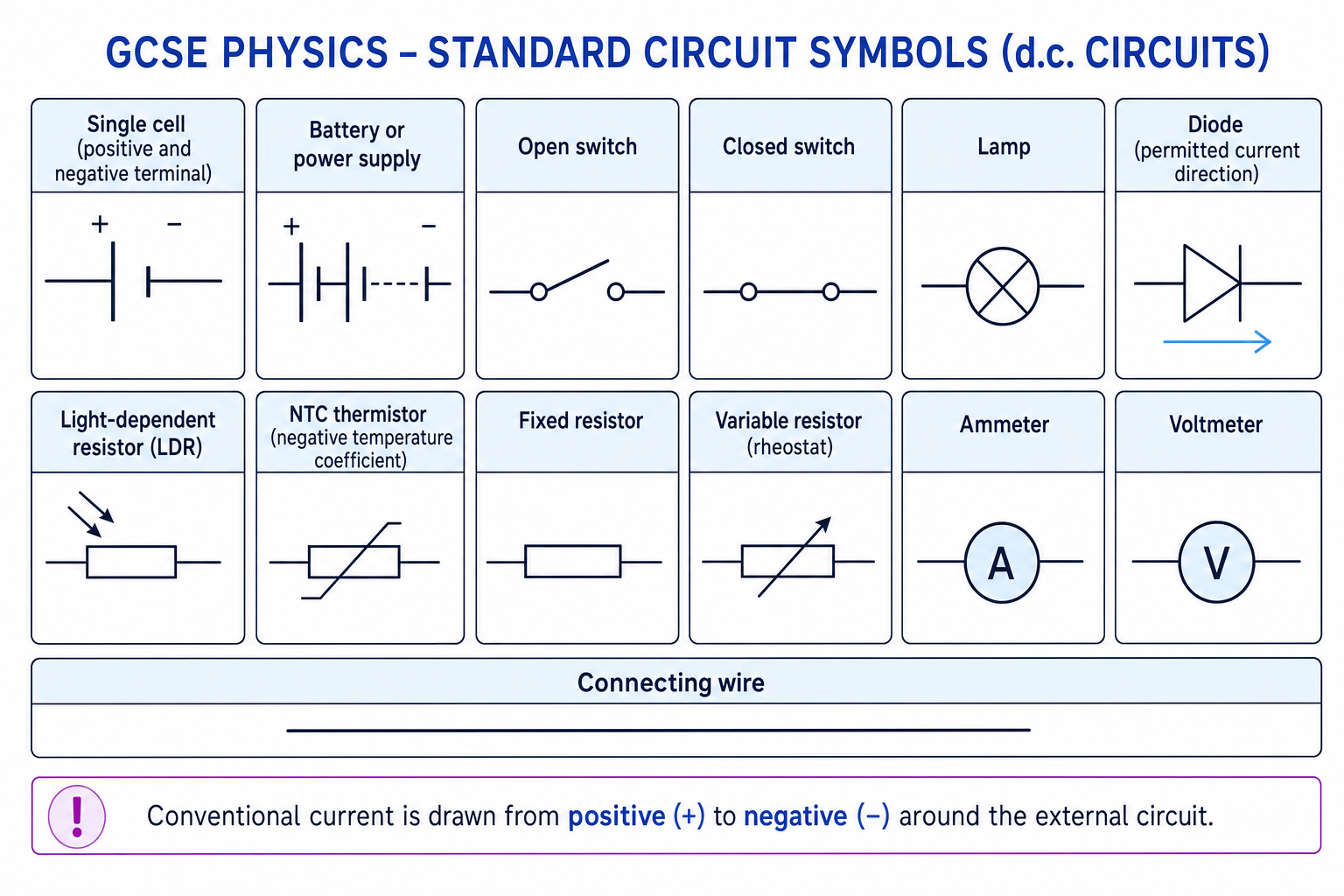
A cell supplies energy to the circuit. A battery is two or more cells. A switch opens or closes the circuit. A fixed resistor has a resistance that is intended to stay constant. A variable resistor lets you change the resistance. A diode allows current mainly in one direction. An LDR changes resistance with light intensity. An NTC thermistor changes resistance with temperature.
2. Measuring current and potential difference
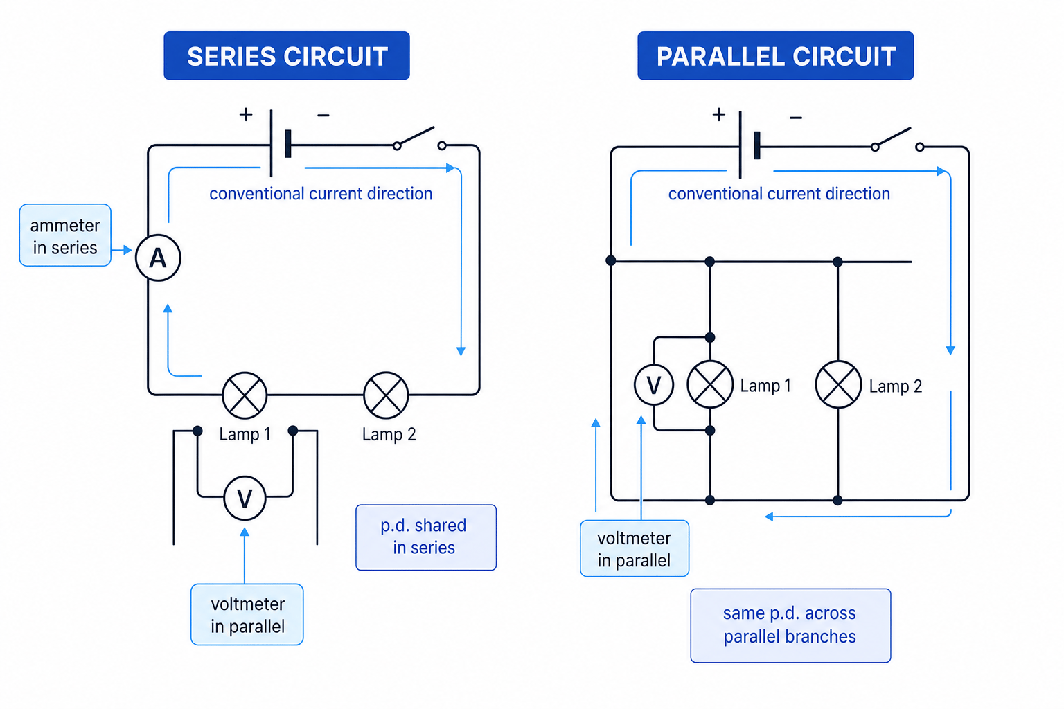
An ammeter measures current. It must be connected in series with the component, so the same current flows through the ammeter and the component.
A voltmeter measures potential difference. It must be connected in parallel across the component, so it compares the energy change between two points.
Definition
Potential difference
Potential difference, or p.d., is the energy transferred per unit charge between two points in a circuit. It is measured in volts, V.
A p.d. of 6 V means each coulomb of charge transfers 6 joules of energy as it moves between those two points.
Common Mistake
Thinking current is used up
Current is not “used up” by components. In a series circuit, the current is the same everywhere. What is transferred in components is energy, shown by a potential difference across them.
3. Resistance and the equation V=IRV=IRV=IR
Resistance is how difficult it is for current to flow through a component. It is measured in ohms, Ω, and has the symbol RRR.
Current depends on both:
- the potential difference across the component, VVV
- the resistance of the component, RRR
For this OCR Gateway section, the following relationship is listed as recall and apply, so you should learn it:
V=IRV = IRV=IRwhere:
- VVV is potential difference in volts, V
- III is current in amperes, A
- RRR is resistance in ohms, Ω
For some resistors, such as a fixed resistor at constant temperature, RRR stays constant. Then current is directly proportional to potential difference.
Example
Calculating current from resistance
A 12 Ω resistor has a potential difference of 6.0 V across it. Calculate the current.
- Use V=IRV = IRV=IR because the question links potential difference, current and resistance.
- Rearrange for current: I=VRI = \frac{V}{R}I=RV.
- Substitute the values, carrying the units:
So the current is 0.50 A.
Tip
Rearranging
The same equation can be rearranged to I=VRI=\frac{V}{R}I=RV or R=VIR=\frac{V}{I}R=IV. If resistance goes up while p.d. stays the same, current goes down.
4. Series circuits
A series circuit has one loop. There is only one path for the current.
In a series circuit:
- the current is the same through every component
- the supply potential difference is shared between components
- the total p.d. across components adds up to the supply p.d.
- resistances add together
For resistors in series:
Rtotal=R1+R2+R3+…R_{\text{total}} = R_1 + R_2 + R_3 + \dotsRtotal=R1+R2+R3+…This is because each resistor makes it harder for charge to flow, so adding more resistors in the same path increases the total resistance.
Example
Solving a series circuit
A 12 V supply is connected to a 4 Ω resistor and an 8 Ω resistor in series. Find the total resistance, the current, and the p.d. across each resistor.
- Add the series resistances:
- Use V=IRV=IRV=IR for the whole circuit:
- Use the same current through each series resistor:
The p.d.s add to 12 V, matching the supply.
5. Parallel circuits
A parallel circuit has branches. Current can split and take more than one path.
In a parallel circuit:
- the p.d. across each branch is the same as the supply p.d.
- the total current is the sum of the currents in the branches
- adding another branch decreases the total resistance
Adding a parallel branch gives charge another route through the circuit. For the same supply p.d., more total current can flow, so the equivalent resistance is lower.
Example
Solving a parallel circuit
A 6.0 V supply is connected to two resistors in parallel: 3.0 Ω and 6.0 Ω. Find the current in each branch, the total current and the equivalent resistance.
- Use the same p.d. across each branch: both resistors have 6.0 V across them.
- Find each branch current using I=VRI=\frac{V}{R}I=RV:
- Add the branch currents:
- Use the whole-circuit values to find equivalent resistance:
The equivalent resistance, 2.0 Ω, is less than either branch resistance.
Common Mistake
Swapping the series and parallel rules
Series circuits have the same current but shared p.d. Parallel circuits have the same p.d. across each branch but split current.
6. Linear and non-linear circuit elements
A linear circuit element has an I–V graph that is a straight line through the origin. This means its resistance is constant.
A non-linear circuit element has a curved I–V graph. Its resistance changes as current, p.d., temperature or light level changes.
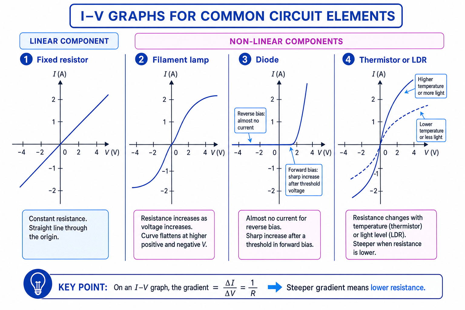
For common components:
- A fixed resistor is linear if its temperature stays constant.
- A filament lamp becomes hotter as current increases, so its resistance increases and the graph flattens.
- A diode has very high resistance in reverse bias and conducts mainly in the forward direction after a threshold p.d.
- An NTC thermistor has lower resistance at higher temperature.
- An LDR has lower resistance in brighter light.
Example
Finding resistance from an I–V graph
A fixed resistor’s graph goes through the origin and the point 4.0 V, 0.80 A. Find its resistance.
- Use one point on the straight-line graph because the resistance is constant.
- Apply R=VIR=\frac{V}{I}R=IV:
- Check the graph meaning: on an I–V graph, a steeper line means more current for the same p.d., so a lower resistance. A resistance of 5.0 Ω is sensible for a fairly steep line.
Common Mistake
Graph gradient depends on the axes
On an I–V graph, the gradient is ΔIΔV\frac{\Delta I}{\Delta V}ΔVΔI, which equals 1R\frac{1}{R}R1. If the graph has V on the vertical axis and I on the horizontal axis, then the gradient is RRR.
7. Designing circuits for testing
To investigate how a component behaves, you usually build a d.c. circuit with:
- the component being tested
- an ammeter in series
- a voltmeter in parallel across the component
- a variable resistor or variable power supply to change the p.d. safely
In practical work such as PAG P6 or P7, you may record current and p.d. for different components, then plot I–V graphs. For a diode, you test forward and reverse directions. For a thermistor, you can change temperature using a water bath. For an LDR, you can change light intensity by moving a lamp or using filters.
Tip
Good measurement habits
Take several readings, avoid very high currents that overheat components, and plot the graph with sensible scales so you can see whether the component is linear or non-linear.
8. Power, energy, charge and time
Power is the rate of energy transfer. It is measured in watts, W, where one watt means one joule per second.
For this OCR Gateway section, these equations are also recall and apply:
E=QVE = QVE=QV P=VIP = VIP=VI P=I2RP = I^2RP=I2R E=PtE = PtE=Ptwhere:
- EEE is energy transferred in joules, J
- QQQ is charge in coulombs, C
- VVV is potential difference in volts, V
- PPP is power in watts, W
- ttt is time in seconds, s
- III is current in amperes, A
- RRR is resistance in ohms, Ω
If power is in kilowatts, kW, and time is in hours, h, then energy is in kilowatt-hours, kWh.
Key Idea
Potential difference links charge and energy
A potential difference tells you how much energy is transferred by each coulomb of charge: E=QVE=QVE=QV. A bigger p.d. means more energy transferred per coulomb.
Example
Calculating power and energy transfer
A lamp has a p.d. of 6.0 V across it and a current of 0.50 A through it. It is switched on for 2 minutes. Calculate the power and energy transferred.
- Use P=VIP=VIP=VI because the question gives p.d. and current:
- Convert the time into seconds:
- Use E=PtE=PtE=Pt:
So the lamp transfers 360 J of energy.
Exam technique
In the exam
- Decide whether the circuit is series or parallel before choosing rules: same current in series, same p.d. in parallel.
- Write the equation first, then substitute values with units; this helps you avoid mixing up VVV, III and RRR.
- For graph questions, check the axes before talking about gradient or resistance.
Self review
Check yourself
- Why does adding a resistor in series increase the total resistance?
- In a parallel circuit, what happens to total current when another branch is added?
- How would you set up a circuit to measure the I–V graph of a filament lamp?

Recap questions
Test yourself with 5 quick questions on this guide. Answer them all correctly to complete it.
Electricity
Guide 2 of 2
You've reached the end
Test yourself on this topic, or move on to the next guide.
How was this guide?