Resistance in series
Definition
Total resistance
The total resistance of a combination of components is the single resistance that would draw the same current from the same supply.
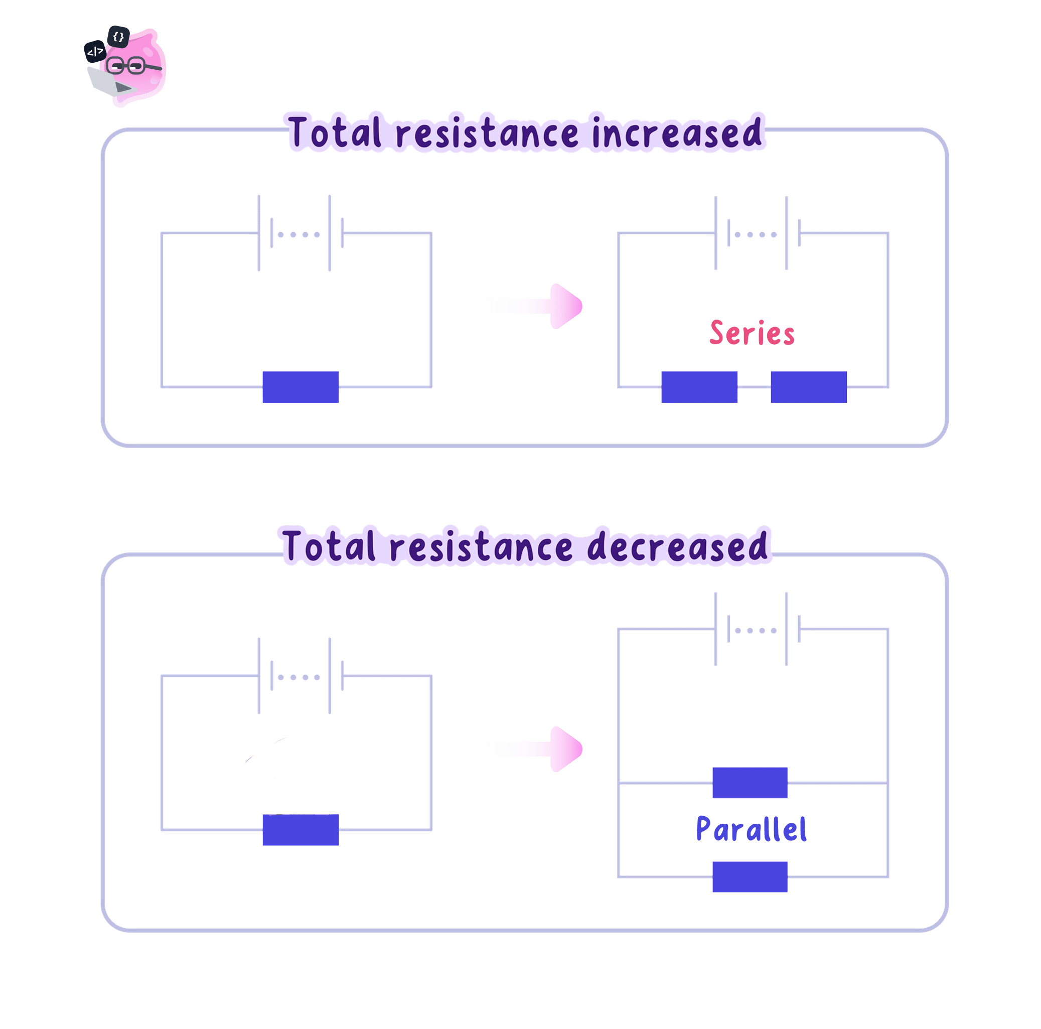
- A series arrangement offers one path only, so the charge must pass through every resistor in turn and meet the opposition of each one on the way.
- The oppositions therefore add, and the total resistance of resistors in series is Rtotal=R1+R2+…R_{\text{total}}=R_{1}+R_{2}+\dotsRtotal=R1+R2+… for any number of them in the loop.
- The total resistance of a series combination is always larger than the largest single resistance within it, because the charge cannot avoid any of them.
- Resistors of 4.0 Ω4.0\ \Omega4.0 Ω and 6.0 Ω6.0\ \Omega6.0 Ω in series give Rtotal=4.0+6.0=10.0 ΩR_{\text{total}}=4.0+6.0=10.0\ \OmegaRtotal=4.0+6.0=10.0 Ω.
- Adding a further resistor in series always raises the total resistance, and no series arrangement can lower it.
- Since the supply potential difference has not changed, I=VRtotalI=\dfrac{V}{R_{\text{total}}}I=RtotalV shows that the current drawn from the supply falls whenever the total resistance rises.
- That smaller current is the same at every point in the single loop, so every component in the series circuit now carries less current than before.
Example
Total resistance in series
- Three resistors of 12 Ω12\ \Omega12 Ω, 18 Ω18\ \Omega18 Ω and 20 Ω20\ \Omega20 Ω are connected in series across a 12 V12\ \text{V}12 V supply.
- The equation for a series combination is Rtotal=R1+R2+R3R_{\text{total}}=R_{1}+R_{2}+R_{3}Rtotal=R1+R2+R3.
- Substitution gives Rtotal=12+18+20=50 ΩR_{\text{total}}=12+18+20=50\ \OmegaRtotal=12+18+20=50 Ω.
- The current follows from I=VRtotalI=\dfrac{V}{R_{\text{total}}}I=RtotalV, so I=1250I=\dfrac{12}{50}I=5012.
- The current drawn from the supply is 0.24 A0.24\ \text{A}0.24 A, and the same 0.24 A0.24\ \text{A}0.24 A passes through each of the three resistors.
Resistance in parallel
- A parallel arrangement gives the charge more than one route, so it no longer has to pass through every resistor.
- Connecting a second branch across the supply gives the charge an extra path while leaving the current in the first branch unchanged, so the total current taken from the supply increases.
- A larger total current for the same supply potential difference can only mean a smaller total resistance, since Rtotal=VItotalR_{\text{total}}=\dfrac{V}{I_{\text{total}}}Rtotal=ItotalV.
- The total resistance of a parallel combination is therefore always smaller than the resistance of the smallest single resistor in it, not somewhere between the values.
- Two identical 10 Ω10\ \Omega10 Ω resistors in parallel across a 10 V10\ \text{V}10 V supply each carry 1.0 A1.0\ \text{A}1.0 A, giving Itotal=2.0 AI_{\text{total}}=2.0\ \text{A}Itotal=2.0 A and Rtotal=102.0=5.0 ΩR_{\text{total}}=\dfrac{10}{2.0}=5.0\ \OmegaRtotal=2.010=5.0 Ω, which is half the resistance of one of them alone.
- A 10 Ω10\ \Omega10 Ω resistor and a 40 Ω40\ \Omega40 Ω resistor in parallel across that same 10 V10\ \text{V}10 V supply carry 1.0 A1.0\ \text{A}1.0 A and 0.25 A0.25\ \text{A}0.25 A, so Itotal=1.25 AI_{\text{total}}=1.25\ \text{A}Itotal=1.25 A and Rtotal=101.25=8.0 ΩR_{\text{total}}=\dfrac{10}{1.25}=8.0\ \OmegaRtotal=1.2510=8.0 Ω, below the smaller of the two values.
- The qualitative argument carries the marks on its own: an extra branch is an extra path for charge, so the combination opposes the flow of charge less than any single branch does.
Common Mistake
- Do not add resistances that are in parallel, because Rtotal=R1+R2R_{\text{total}}=R_{1}+R_{2}Rtotal=R1+R2 applies only to a series arrangement.
- Do not expect the total resistance of a parallel pair to lie between the two values, since it always falls below the smaller of them.
- Do not claim the current in an existing parallel branch drops when a new branch is added, as that branch still has the full supply potential difference across it.
- Do not use the total resistance to find a single branch current, because a branch current depends only on that branch's own resistance.
Changing the circuit
- Adding a resistor in series raises the total resistance, so the current falls at every point in that loop.
- Removing a resistor from a series loop lowers the total resistance, so the current rises at every point in that loop.
- Adding a branch in parallel lowers the total resistance, so the total current drawn from the supply rises.
- Removing a parallel branch raises the total resistance and lowers the total current, while every remaining branch carries exactly the current it carried before.
- A switch in series that opens makes the resistance of the loop effectively infinite, so the current everywhere in that loop falls to zero.
- A wire joined straight across a resistor offers a path of almost no resistance, so nearly all of the current takes the wire and the total resistance of the circuit drops sharply.
Exam technique
Series and parallel answers
- Quote Rtotal=R1+R2+…R_{\text{total}}=R_{1}+R_{2}+\dotsRtotal=R1+R2+… before adding anything, and say that it applies because the resistors are in series.
- For a parallel combination, state that the total resistance is less than the smallest branch resistance and give the extra-path reason.
- Find a branch current from I=VRI=\dfrac{V}{R}I=RV using that branch's own resistance together with the supply potential difference.
- Name both the change and its effect, such as that a third lamp in series raises the total resistance and so lowers the current, making every lamp dimmer.
- Convert kilohms into ohms before adding, so 1.2 kΩ1.2\ \text{k}\Omega1.2 kΩ in series with 800 Ω800\ \Omega800 Ω gives 2000 Ω2000\ \Omega2000 Ω.
Lamp brightness
- How brightly a lamp glows depends on the current through it and the potential difference across it, so anything that changes the total resistance changes the brightness.
- Two matched lamps in series across a 6 V6\ \text{V}6 V supply give a total resistance of twice one lamp, so the current is about half what a single lamp on its own would take.
- Each lamp in that series pair also has only about 3 V3\ \text{V}3 V across it instead of the full 6 V6\ \text{V}6 V, so the two glow dimly and equally.
- The same two lamps reconnected in parallel across that 6 V6\ \text{V}6 V supply each have the whole 6 V6\ \text{V}6 V across them, and each carries the current that a single lamp would take.
- Identical lamps are therefore brighter in parallel than in series for the same supply, and the parallel arrangement draws about twice the total current because its total resistance is about half that of one lamp.
Practical
Testing series and parallel circuits
- Aim: to test how current and potential difference behave in series and in parallel circuits built from the same two matched filament lamps.
- Apparatus: a low-voltage d.c. supply or a battery of cells, two matched filament lamps in holders, a fixed resistor, an ammeter, a voltmeter, a switch and connecting leads.
- Variables: the circuit arrangement, series or parallel, is the independent variable; the ammeter and voltmeter readings are the dependent variables; the same two lamps, the same supply setting and the same leads are kept the same throughout.
- Method, set-up:
- Draw the circuit diagram first, then build a single series loop containing the supply, the switch, the ammeter and both lamps.
- Set the supply to a low value such as 6 V6\ \text{V}6 V and push every connection home firmly, leaving the switch open.
- Have the circuit checked before the supply is switched on.
- Method, the series circuit:
- Close the switch briefly with the ammeter between the supply and the first lamp, and record the reading.
- Open the switch, move the ammeter to between the two lamps, close the switch again and record the current at that position.
- Repeat with the ammeter between the second lamp and the supply, so the current has been measured at three positions in the loop.
- Connect the voltmeter across the first lamp and record V1V_{1}V1, then across the second lamp for V2V_{2}V2, then across the supply terminals for VsupplyV_{\text{supply}}Vsupply.
- Note how brightly each lamp glows, then repeat every reading at least twice and take a mean.
- Method, the parallel circuit:
- Switch off and rebuild the circuit with the same two lamps on separate branches connected across the supply.
- Put the ammeter in the main branch, between the supply and the first junction, and record ItotalI_{\text{total}}Itotal.
- Move the ammeter into each branch in turn and record I1I_{1}I1 and I2I_{2}I2.
- Connect the voltmeter across each branch and then across the supply, and note the brightness of the lamps again.
- Results: in series the current is the same at all three positions and the lamp potential differences add to the supply value, V1+V2=VsupplyV_{1}+V_{2}=V_{\text{supply}}V1+V2=Vsupply; in parallel each branch has the full supply potential difference across it and the branch currents add, I1+I2=ItotalI_{1}+I_{2}=I_{\text{total}}I1+I2=Itotal.
- Maths: find each lamp's resistance from R=VIR=\dfrac{V}{I}R=IV, add the series values with Rtotal=R1+R2R_{\text{total}}=R_{1}+R_{2}Rtotal=R1+R2, then work out the parallel total from Rtotal=VsupplyItotalR_{\text{total}}=\dfrac{V_{\text{supply}}}{I_{\text{total}}}Rtotal=ItotalVsupply and check that it comes out below the resistance of either lamp on its own.
- Watch out: the matched lamps are visibly brighter in parallel than in series for the same supply, because the parallel total resistance is lower and each lamp then has the whole supply potential difference across it. A lamp's resistance rises as its filament heats, so readings taken while it is still warming will drift.
- Meter resolution, a zero error on either meter, loose contacts and the internal resistance of the supply all keep the readings from adding up exactly.
- Use digital meters on a suitable range, secure every contact, repeat each reading and open the switch between readings so the lamps do not sit and heat up.
- Safety: use a low-voltage supply only, switch off before changing any connection, avoid short circuits across the supply and do not touch a lamp or resistor that has been carrying current.
Self review
- State the equation for the total resistance of resistors in series and give the unit.
- Calculate the total resistance of 15 Ω15\ \Omega15 Ω, 25 Ω25\ \Omega25 Ω and 30 Ω30\ \Omega30 Ω in series, then the current drawn from a 14 V14\ \text{V}14 V supply.
- Explain why the total resistance of two resistors in parallel is less than the smaller of the two.
- State what happens to the total current when one parallel branch is disconnected, and why.
- Explain why two matched lamps are brighter in parallel than in series across the same supply.