Current-potential difference graphs
Current-potential difference graph
A current-potential difference graph is a plot of the current through a component against the potential difference across it, used to show how its resistance behaves.
Ohmic conductor
An ohmic conductor is a component whose resistance stays constant, so the current through it is directly proportional to the potential difference across it.
- A current-potential difference graph is built up by changing the potential difference across one component in steps and recording the current through it at each step.
- The current goes on the vertical axis and the potential difference on the horizontal axis, so the finished graph is a picture of how that one component behaves.
- Reversing the supply gives negative values of both quantities, so a full characteristic runs through the origin and into the third quadrant as well as the first.
- A steeper plot at a given potential difference means a larger current, and a larger current for the same potential difference means a smaller resistance, since R=VIR=\dfrac{V}{I}R=IV.
- An ohmic conductor gives a straight line through the origin, and its resistance works out the same at every point along that line.
- Any component whose graph curves is non-ohmic, because R=VIR=\dfrac{V}{I}R=IV then gives a different value at different points on the graph.
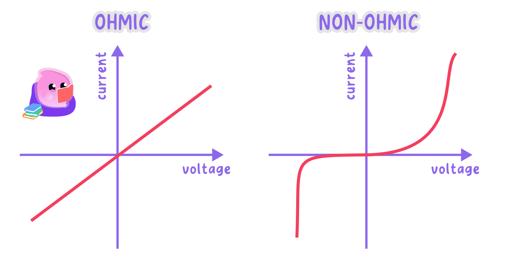
The shape of a current-potential difference graph shows whether a component's resistance stays constant, so only a straight line through the origin identifies an ohmic conductor.
The fixed resistor
- A fixed resistor held at constant temperature is an ohmic conductor, so its graph is a straight line passing through the origin.
- The line carries straight on into the negative region, because a resistor behaves in exactly the same way whichever direction the current takes.
- Current is directly proportional to potential difference for this component, so doubling the potential difference doubles the current and halving it halves the current.
- The resistance at any point on the graph is R=VIR=\dfrac{V}{I}R=IV, and every point on the same straight line returns the same value.
- The points (2.0 V, 0.10 A)(2.0\ \text{V},\ 0.10\ \text{A})(2.0 V, 0.10 A) and (6.0 V, 0.30 A)(6.0\ \text{V},\ 0.30\ \text{A})(6.0 V, 0.30 A) both give R=20 ΩR=20\ \OmegaR=20 Ω, which is what a constant resistance looks like on a graph.
- If the current is allowed to grow large enough to warm the resistor, its resistance rises and the line starts to bend, so readings are taken quickly at low current with the switch opened in between.
Resistance from a straight line
- A straight line through the origin passes through the point where the potential difference is 4.0 V4.0\ \text{V}4.0 V and the current is 0.16 A0.16\ \text{A}0.16 A.
- The resistance at a point on a graph is given by R=VIR=\dfrac{V}{I}R=IV.
- Substitution gives R=4.00.16R=\dfrac{4.0}{0.16}R=0.164.0.
- The resistance is R=25 ΩR=25\ \OmegaR=25 Ω.
- The point (8.0 V, 0.32 A)(8.0\ \text{V},\ 0.32\ \text{A})(8.0 V, 0.32 A) on the same line also gives 25 Ω25\ \Omega25 Ω, which confirms that the component is an ohmic conductor.
The filament lamp
Filament lamp
A filament lamp is a lamp that emits light because the current heats a thin coiled metal wire until it glows.
- A filament lamp gives a curve through the origin whose gradient decreases as the potential difference rises, so the plot flattens off towards each end.
- A larger potential difference drives a larger current, so more electrons pass through the thin metal filament every second.
- Those electrons collide more often with the vibrating positive ions of the filament's lattice, and each collision transfers energy from an electron to an ion.
- The ions therefore vibrate more strongly, so the internal energy and the temperature of the filament rise, reaching well over 1000 ∘C1000\,^{\circ}\text{C}1000∘C in a lamp that is glowing.
- Ions vibrating through larger distances get in the way of the drifting electrons more often, so collisions become still more frequent and the resistance of the filament increases.
- Because the resistance climbs as the lamp heats, each extra volt produces less extra current than the volt before it, and that is exactly why the curve flattens.
- The curve has the same shape on both sides of the origin, because the heating of the filament does not depend on which way the current passes through it.
Resistance of a hot filament
- A filament lamp characteristic passes through the points (2.0 V, 0.25 A)(2.0\ \text{V},\ 0.25\ \text{A})(2.0 V, 0.25 A) and (8.0 V, 0.40 A)(8.0\ \text{V},\ 0.40\ \text{A})(8.0 V, 0.40 A).
- The resistance at a point comes from R=VIR=\dfrac{V}{I}R=IV, using the coordinates of the point and not the gradient of the curve.
- At the first point, R=2.00.25=8.0 ΩR=\dfrac{2.0}{0.25}=8.0\ \OmegaR=0.252.0=8.0 Ω.
- At the second point, R=8.00.40=20 ΩR=\dfrac{8.0}{0.40}=20\ \OmegaR=0.408.0=20 Ω.
- The resistance has risen from 8.0 Ω8.0\ \Omega8.0 Ω to 20 Ω20\ \Omega20 Ω because the filament is far hotter at the larger potential difference.
The diode
Diode
A diode is a component that allows current to flow through it in one direction only.
- A diode allows current to pass in one direction only, the forward direction shown by the arrowhead in its circuit symbol.
- Connected in reverse, a diode has an extremely high resistance, so its graph lies along the horizontal axis with a current of practically zero.
- Connected forwards, almost no current passes until the potential difference reaches about 0.6 V0.6\ \text{V}0.6 V, so the graph stays close to the axis over that first stretch.
- Above about 0.6 V0.6\ \text{V}0.6 V the current rises very steeply, which means the resistance of the diode has dropped sharply.
- The characteristic is neither a straight line nor symmetrical about the origin, so a diode is not an ohmic conductor.
- A light-emitting diode has the same shaped characteristic and gives out light once it conducts, and a diode placed in series protects a component that a reversed supply would damage.
- Do not take the resistance of a filament lamp or a diode from the gradient of the curve, because the gradient of a curve changes from point to point.
- Do not call a filament lamp ohmic just because its graph passes through the origin, since an ohmic conductor has to give a straight line as well.
- Do not write that the resistance of a lamp falls as it grows brighter, because the resistance rises as the filament gets hotter.
- Do not sketch a diode characteristic rising straight from the origin, as the forward current stays near zero until about 0.6 V0.6\ \text{V}0.6 V.
Reading a graph
- Identify the axes first, then decide whether the plot is a straight line, a smooth curve, or a flat section followed by a sudden rise.
- A straight line through the origin belongs to a fixed resistor at constant temperature, a curve flattening at both ends belongs to a filament lamp, and a flat section with a steep rise in one direction only belongs to a diode.
- Read a pair of coordinates off the axes and use R=VIR=\dfrac{V}{I}R=IV to get the resistance at that point, always stating which point was used.
- For a straight line only, the gradient of the graph equals 1R\dfrac{1}{R}R1, so a steeper straight line means a smaller resistance.
Answering graph questions
- Name the component and describe the shape before explaining anything, using wording such as a curve with a decreasing gradient.
- Quote R=VIR=\dfrac{V}{I}R=IV and give the coordinates used, so the source of each substituted value is visible.
- Give the full chain for a filament lamp: larger current, more collisions with the vibrating ions, higher temperature, higher resistance.
- Use directly proportional only for the fixed resistor's straight line through the origin.
- State that a diode conducts in one direction only, and quote the turn-on value of about 0.6 V0.6\ \text{V}0.6 V when the graph shows it.
Measuring current and potential difference
- Aim: to find how the current depends on the potential difference for a fixed resistor and then for a filament lamp, and to calculate the resistance of each from the readings.
- Apparatus: a low-voltage d.c. power supply or a battery of cells, a fixed resistor, a filament lamp in a holder, a variable resistor, an ammeter, a voltmeter, a switch, connecting leads and a reversing switch if a full characteristic is wanted.
- Variables: the potential difference across the test component is the independent variable, the current through it is the dependent variable, and the component on test, the supply and the surroundings are kept the same across one set of readings.
- Method, set-up:
- Draw the circuit diagram first: the supply, the switch, the ammeter, the variable resistor and the test component all in one series loop.
- Connect the voltmeter in parallel across the test component alone, so it reads the potential difference across that component and nothing else.
- Check that both meters are connected the right way round for a d.c. supply, and set the variable resistor to its largest resistance.
- Have the circuit checked before switching on, and leave the switch open until then.
- Method, the fixed resistor:
- Close the switch briefly, read the ammeter and the voltmeter at the same instant, record both values, then open the switch again.
- Move the variable resistor slider a little to change the potential difference and take the next pair of readings the same way.
- Collect at least six pairs of readings spread across the available range, opening the switch between each pair so the resistor does not warm up.
- Reverse the connections at the supply, or throw the reversing switch, and repeat to collect negative pairs of readings for the other half of the characteristic.
- Method, the filament lamp:
- Switch off, take the fixed resistor out and put the filament lamp in its place, leaving the rest of the circuit untouched.
- Repeat the whole set of readings, waiting a few seconds after each pair so the filament cools back towards a steady temperature.
- Take extra pairs of readings at low potential difference, where the curve bends most sharply and a gap in the data is most obvious.
- Results: the fixed resistor gives a straight line through the origin, so its resistance is constant; the filament lamp gives a curve whose gradient decreases as the potential difference rises, because the resistance of the filament increases as it gets hotter.
- Maths: calculate the resistance at chosen points from R=VIR=\dfrac{V}{I}R=IV using coordinates read off the graph, plot current on the vertical axis against potential difference on the horizontal axis, and draw one smooth line or curve of best fit through both the positive and the negative readings.
- Watch out: read the ammeter and the voltmeter at the same moment, because both readings drift as soon as the component starts to warm. Take the resistance of the lamp from a pair of coordinates rather than from the gradient of the curve.
- Meter resolution, a zero error on either meter, loose contacts and the internal resistance of the supply all limit how close the readings come to the true values.
- Use digital meters on a suitable range, push every connection home, repeat each pair of readings and keep the switch open in between so heating is limited.
- Safety: use a low-voltage supply only, switch off before changing any connection, avoid short circuits across the supply and do not touch the lamp or the resistor after current has passed through it.
- State what a graph must look like for a component to be an ohmic conductor.
- A straight line through the origin passes through (3.0 V, 0.12 A)(3.0\ \text{V},\ 0.12\ \text{A})(3.0 V, 0.12 A). Calculate the resistance.
- Explain in full why the resistance of a filament lamp increases as the potential difference across it rises.
- Describe the shape of a diode characteristic in both the forward and the reverse direction.
- Explain why the resistance of a lamp at a point is found from coordinates and not from the gradient of the curve.