10.2.1 Current in a circuit and conservation at junctions
Current in a series circuit
Conservation of charge
Conservation of charge is the rule that charge is never created or destroyed in a circuit, so the total current entering a junction equals the total current leaving it.
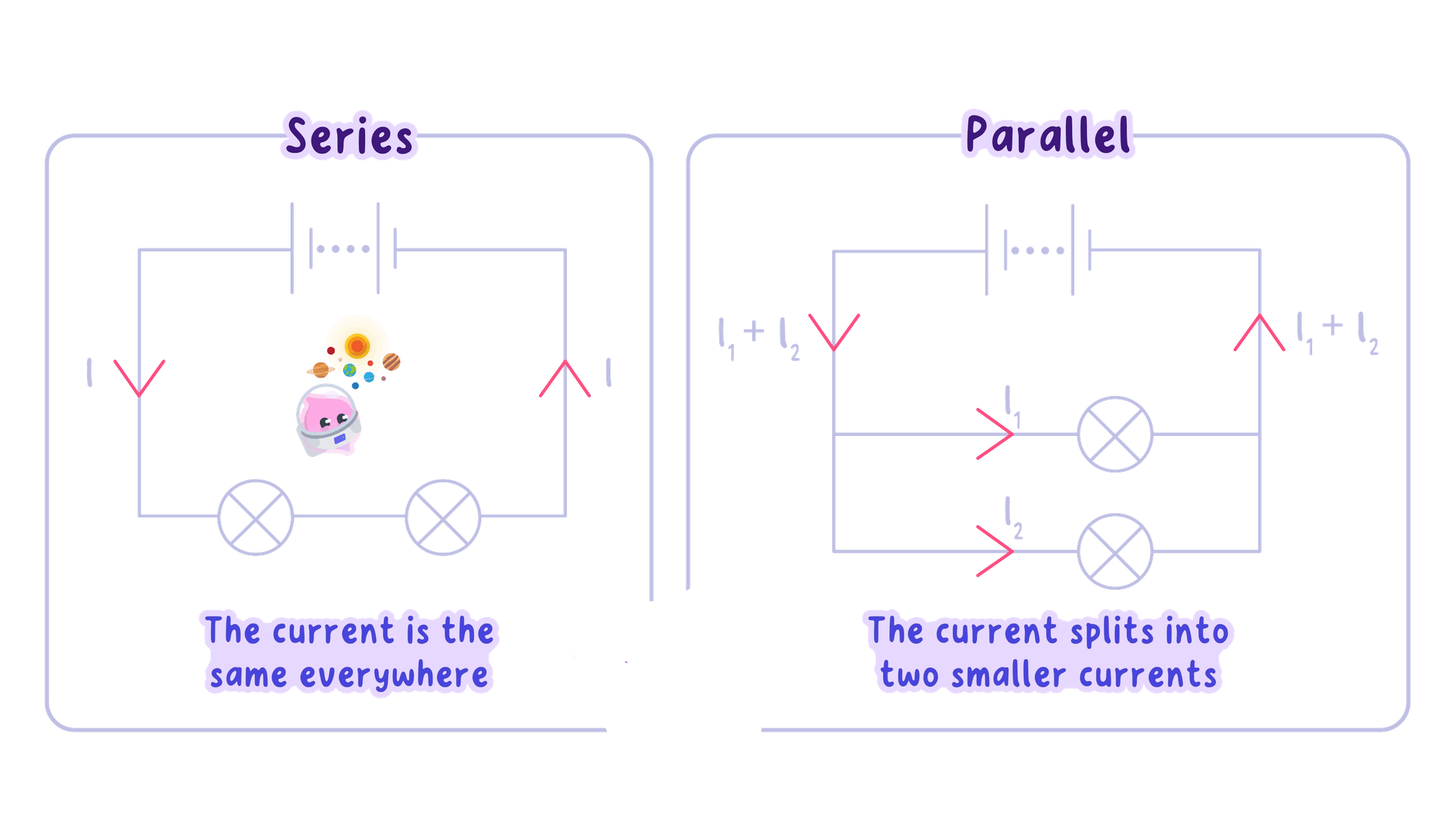
- A series circuit is a single loop, so there is only one path available and every charge carrier that leaves the supply must travel through every component in turn.
- Current is the rate at which charge passes a point in the circuit, and in a metal wire the moving charge is the delocalised electrons.
- Charge cannot leak out through the insulation of a wire, and it cannot pile up inside a wire or inside a component, because charge is conserved.
- Every coulomb of charge that passes one point in the loop must therefore pass every other point in the same loop, so the current is the same at every point in a series circuit.
- Edexcel answers earn credit for the reason as well as the statement, so the wording to use is that the current is the same everywhere because charge is conserved and cannot be used up.
- A component does not use up current. A filament lamp takes energy from the charge passing through it, which is why there is a potential difference across the lamp, but exactly as many electrons leave the lamp each second as enter it.
- An ammeter gives the same reading wherever it is placed in a series loop, so a meter reading 0.25 A0.25\ \text{A}0.25 A before a lamp will still read 0.25 A0.25\ \text{A}0.25 A after that lamp.
The current is the same at every point in a series circuit because charge is conserved: it is not created, destroyed or stored anywhere in the loop.
Junctions in a circuit
Junction
A junction is a point in a circuit where three or more wires meet, so the path for the charge either divides or joins together again.
- A junction is a point where three or more wires meet, so a single path divides into branches or several branches combine into one.
- Charge arriving at a junction has nowhere to collect, because a wire and a junction cannot store charge.
- The total current into a junction is equal to the total current out of it, and this statement is called the junction rule.
- Written with symbols the rule is Iin=IoutI_{\text{in}}=I_{\text{out}}Iin=Iout, so a current III that divides into two branch currents obeys I=I1+I2I=I_{1}+I_{2}I=I1+I2.
- The rule is a direct consequence of the conservation of charge, since no charge is created or destroyed at the meeting point.
- The rule works in both directions, so where two branches rejoin, the currents add again to give I1+I2=II_{1}+I_{2}=II1+I2=I in the wire returning to the supply.
Currents at a junction
- A wire carries a current of 0.90 A0.90\ \text{A}0.90 A into a junction, and three branches lead away from it. Two of the branch ammeters read 0.30 A0.30\ \text{A}0.30 A and 0.25 A0.25\ \text{A}0.25 A, and the third branch current I3I_{3}I3 is unknown.
- The junction rule states Iin=IoutI_{\text{in}}=I_{\text{out}}Iin=Iout, which gives 0.90=0.30+0.25+I30.90=0.30+0.25+I_{3}0.90=0.30+0.25+I3.
- Rearranging for the unknown gives I3=0.90−0.30−0.25I_{3}=0.90-0.30-0.25I3=0.90−0.30−0.25.
- Substitution gives I3=0.35 AI_{3}=0.35\ \text{A}I3=0.35 A.
- The ammeter in the third branch therefore reads 0.35 A0.35\ \text{A}0.35 A.
Current in parallel branches
- In a parallel circuit the charge leaving the supply reaches a junction and divides between the branches, with each branch taking a share of the total.
- The shares recombine at the junction on the far side of the branches, and the recombined current returns to the supply.
- The branch currents add to give the total, so Itotal=I1+I2+…I_{\text{total}}=I_{1}+I_{2}+\dotsItotal=I1+I2+… for any number of branches.
- An ammeter placed in the main branch, between the supply and the first junction, reads ItotalI_{\text{total}}Itotal.
- An ammeter moved into one branch reads only that branch's current, which is always smaller than the main-branch reading whenever more than one branch is connected.
- Each branch is itself a small series path, so two ammeters placed on either side of the same lamp within one branch give identical readings.
- For example, if two branches carry 0.40 A0.40\ \text{A}0.40 A and 0.60 A0.60\ \text{A}0.60 A, then the main branch carries Itotal=0.40+0.60=1.00 AI_{\text{total}}=0.40+0.60=1.00\ \text{A}Itotal=0.40+0.60=1.00 A.
Unequal branches
- The current only divides equally between parallel branches when the branches are identical, which is not the general case.
- Every branch of a parallel section has the same potential difference across it, equal to the potential difference of the supply.
- With the same potential difference across each branch, I=VRI=\dfrac{V}{R}I=RV shows that a branch's current is fixed by that branch's own resistance and by nothing else.
- The branch of lower resistance therefore carries the larger current, and the branch of higher resistance carries the smaller current.
- With a 12 V12\ \text{V}12 V supply, a branch of resistance 6 Ω6\ \Omega6 Ω carries I=126=2.0 AI=\dfrac{12}{6}=2.0\ \text{A}I=612=2.0 A while a branch of resistance 24 Ω24\ \Omega24 Ω carries I=1224=0.50 AI=\dfrac{12}{24}=0.50\ \text{A}I=2412=0.50 A, giving Itotal=2.5 AI_{\text{total}}=2.5\ \text{A}Itotal=2.5 A.
- Three identical lamps in parallel across one supply each carry one third of the main-branch current, so a main-branch reading of 0.60 A0.60\ \text{A}0.60 A means 0.20 A0.20\ \text{A}0.20 A in each branch.
- A break in one branch stops the current in that branch alone. The surviving branches keep exactly the current they had, and the junction rule then gives a smaller total current in the main branch.
- Do not write that a component uses up current, because the same charge per second leaves a lamp as enters it.
- Do not assume the current splits equally at a junction, since equal shares only occur when the branches have equal resistance.
- Do not add readings together for components in series, because a single loop has one path and therefore one current.
- Do not treat a branch ammeter reading as the total, as only a meter in the main branch reads ItotalI_{\text{total}}Itotal.
Predicting ammeter readings
- Mark every junction on the diagram with a dot, then write on each current that is already known together with an arrow showing its direction.
- Fill in any series section next, because one reading in a series section fixes every other reading in that same section.
- At a junction with one unknown, subtract the known outgoing currents from the incoming current, or add the branch currents to find the incoming one.
- Quote each reading to the resolution of the meter, so a meter reading to the nearest 0.01 A0.01\ \text{A}0.01 A gives an answer such as 0.35 A0.35\ \text{A}0.35 A rather than 0.4 A0.4\ \text{A}0.4 A.
- Finish by checking that the junction rule balances at every junction in the circuit, not only at the one used to find the unknown.
Answering current questions
- State the rule being used before any numbers appear, such as that the current is the same at every point in a series loop.
- Give the reason as well as the statement, because the mark for the explanation sits on conservation of charge.
- Convert milliamps to amps before adding branch currents, so 250 mA250\ \text{mA}250 mA is written as 0.250 A0.250\ \text{A}0.250 A.
- Say which ammeter a value belongs to, since a main-branch reading and a branch reading are different quantities.
- When asked to compare branches, name the resistance of each branch as the cause of the difference in current.
- State what happens to the current at each point in a series circuit and give the reason.
- State the junction rule in words and in symbols.
- A main branch carries 1.20 A1.20\ \text{A}1.20 A into two branches, one of which carries 0.45 A0.45\ \text{A}0.45 A. Find the other branch current.
- Explain why the branch with the lower resistance carries the larger current.
- Explain what happens to the current in the remaining branches when one parallel branch breaks.
10.2.2 Resistance and variable resistors
What resistance is
Resistance
Resistance is the opposition of a component to the flow of charge, equal to the potential difference across it divided by the current through it.
Ohm
One ohm is the resistance of a component that carries a current of one ampere when a potential difference of one volt is applied across it.
- Resistance is the opposition a component offers to the flow of charge through it, so a large resistance means it is hard to drive a current through that component.
- In a metal the delocalised electrons are free to drift when a potential difference is applied, but the positive metal ions are held in a fixed regular arrangement called the lattice and are vibrating about their positions.
- As the electrons drift they collide with these vibrating positive ions, and every collision transfers energy from the electrons to the ions and slows the electrons down.
- Resistance is therefore a measure of how often the electrons collide on their way through the material, so more frequent collisions mean a larger resistance.
- The unit of resistance is the ohm, written Ω\OmegaΩ, and a component has a resistance of 1 Ω1\ \Omega1 Ω when a potential difference of 1 V1\ \text{V}1 V across it drives a current of 1 A1\ \text{A}1 A through it.
- A short copper connecting lead has a resistance of a small fraction of an ohm, a filament lamp a few ohms, and the plastic sheath around that lead many millions of ohms, which is why virtually no current passes through the sheath.
For a fixed potential difference a larger resistance always gives a smaller current, because the charge meets more opposition on its way round the circuit.
The resistance equation
- The three quantities are linked by V=IRV=IRV=IR, where VVV is the potential difference across the component in volts, III is the current through it in amperes and RRR is its resistance in ohms.
- All three values must belong to the same component, so VVV is the potential difference measured across it and III is the current measured through it.
- The rearrangements are I=VRI=\dfrac{V}{R}I=RV and R=VIR=\dfrac{V}{I}R=IV, and the form to choose depends only on which of the three quantities is unknown.
- Reading the equation in the form R=VIR=\dfrac{V}{I}R=IV shows that an ohm is a volt per ampere, so 1 Ω=1 V A−11\ \Omega=1\ \text{V A}^{-1}1 Ω=1 V A−1.
- Every value must be converted into volts, amperes and ohms before substitution, so 250 mA250\ \text{mA}250 mA becomes 0.250 A0.250\ \text{A}0.250 A and 4.7 kΩ4.7\ \text{k}\Omega4.7 kΩ becomes 4700 Ω4700\ \Omega4700 Ω.
- Quoting the equation before substituting earns credit in its own right, so the equation is written out even when the arithmetic that follows is wrong.
Finding a potential difference
- A resistor of resistance 47 Ω47\ \Omega47 Ω carries a current of 120 mA120\ \text{mA}120 mA.
- The current is converted into amperes first, giving 120 mA=0.120 A120\ \text{mA}=0.120\ \text{A}120 mA=0.120 A.
- The equation needed is V=IRV=IRV=IR, and no rearrangement is required.
- Substitution gives V=0.120×47V=0.120\times 47V=0.120×47.
- The potential difference across the resistor is V=5.6 VV=5.6\ \text{V}V=5.6 V to two significant figures.
Current and resistance
- With the potential difference held constant, I=VRI=\dfrac{V}{R}I=RV shows that the current is inversely proportional to the resistance.
- Doubling the resistance therefore halves the current, and tripling the resistance reduces the current to one third of its original value.
- At a fixed 6.0 V6.0\ \text{V}6.0 V, a resistance of 2.0 Ω2.0\ \Omega2.0 Ω gives I=3.0 AI=3.0\ \text{A}I=3.0 A, a resistance of 6.0 Ω6.0\ \Omega6.0 Ω gives I=1.0 AI=1.0\ \text{A}I=1.0 A and a resistance of 12 Ω12\ \Omega12 Ω gives I=0.50 AI=0.50\ \text{A}I=0.50 A.
- The product IRIRIR comes to 6.0 V6.0\ \text{V}6.0 V in each of those three cases, which is exactly what V=IRV=IRV=IR says.
- With the resistance held constant instead, I=VRI=\dfrac{V}{R}I=RV shows the current is directly proportional to the potential difference, so doubling the supply potential difference doubles the current.
- The phrase directly proportional is only justified when two quantities give a straight line through the origin, so it fits III against VVV at constant resistance but never fits III against RRR, whose graph is a curve.
Finding a current
- A potential difference of 12 V12\ \text{V}12 V is applied across a resistor of resistance 1.5 kΩ1.5\ \text{k}\Omega1.5 kΩ.
- The resistance is converted into ohms, giving 1.5 kΩ=1500 Ω1.5\ \text{k}\Omega=1500\ \Omega1.5 kΩ=1500 Ω.
- The equation V=IRV=IRV=IR is rearranged to make the current the subject, I=VRI=\dfrac{V}{R}I=RV.
- Substitution gives I=121500I=\dfrac{12}{1500}I=150012.
- The current is I=0.0080 AI=0.0080\ \text{A}I=0.0080 A, which is the same as 8.0 mA8.0\ \text{mA}8.0 mA.
Measuring resistance
- Resistance cannot be read straight off a meter, so it is worked out from one pair of readings using R=VIR=\dfrac{V}{I}R=IV.
- The circuit is a single loop holding a low-voltage supply, a switch, an ammeter and the component whose resistance is wanted.
- The ammeter is placed in series with the component, so the current it reads is exactly the current passing through that component.
- The voltmeter is connected in parallel across the component on its own, so the value it reads is the potential difference across that component and not across the whole circuit.
- The switch is closed only briefly and both meters are read at the same moment, so the pair of values belongs to the same instant.
- With readings of V=4.5 VV=4.5\ \text{V}V=4.5 V and I=0.30 AI=0.30\ \text{A}I=0.30 A, the equation R=VIR=\dfrac{V}{I}R=IV gives R=4.50.30=15 ΩR=\dfrac{4.5}{0.30}=15\ \OmegaR=0.304.5=15 Ω.
- Repeating the pair of readings and taking a mean reduces the effect of random error, and keeping the current small stops the component warming up and changing its resistance while it is being measured.
- Do not connect the voltmeter in series with the component, because a voltmeter has a very high resistance and would cut the current in the loop almost to zero.
- Do not put the supply potential difference into R=VIR=\dfrac{V}{I}R=IV when the component is one of several in the loop, since only part of that potential difference is across the component being tested.
- Do not substitute values in milliamps or kilohms, because V=IRV=IRV=IR only balances when the units are volts, amperes and ohms.
- Do not write that the current uses up the resistance, as resistance is a property of the component itself.
Variable resistors
Variable resistor
A variable resistor is a resistor whose resistance can be adjusted, which changes the current in the circuit it is connected in.
- A variable resistor holds a length of resistance wire with a sliding contact, and only the part of the wire between that contact and one end terminal is included in the circuit.
- Moving the slider so that more of the wire is included increases the resistance that the charge has to pass through.
- The variable resistor sits in series with the rest of the loop, so raising its resistance raises the resistance of the whole loop and lowers the current at every point in it.
- Moving the slider the other way includes less wire, lowers the resistance and raises the current, which is why a single control can be turned smoothly from one extreme to the other.
- That is how a variable resistor dims a lamp, sets the speed of a small motor and adjusts the volume of a loudspeaker.
- In a measuring circuit it provides a whole range of current and potential difference pairs from one fixed supply, and it is set to its largest resistance before the switch is closed so that the first current is small.
Using the resistance equation
- Write V=IRV=IRV=IR out in full first, then show the rearranged form on a separate line before any numbers appear.
- Convert every value into volts, amperes and ohms before substituting, and show the conversion.
- Name both the change and its effect when describing a variable resistor, such as that including more resistance wire raises the resistance and so lowers the current.
- State which component a reading belongs to whenever a question gives more than one potential difference.
- Give the unit with the final answer, because a bare number earns nothing.
- Define resistance and give its unit and the symbol for that unit.
- Explain, in terms of electrons and the vibrating positive ions of a metal, why a metal wire has resistance.
- Calculate the potential difference across a 22 Ω22\ \Omega22 Ω resistor carrying a current of 0.25 A0.25\ \text{A}0.25 A.
- Calculate the resistance of a component with 9.0 V9.0\ \text{V}9.0 V across it and 0.45 A0.45\ \text{A}0.45 A through it.
- Explain how moving the slider of a variable resistor changes the current in a series loop.
10.2.3 Series and parallel resistance
Resistance in series
Total resistance
The total resistance of a combination of components is the single resistance that would draw the same current from the same supply.
- A series arrangement offers one path only, so the charge must pass through every resistor in turn and meet the opposition of each one on the way.
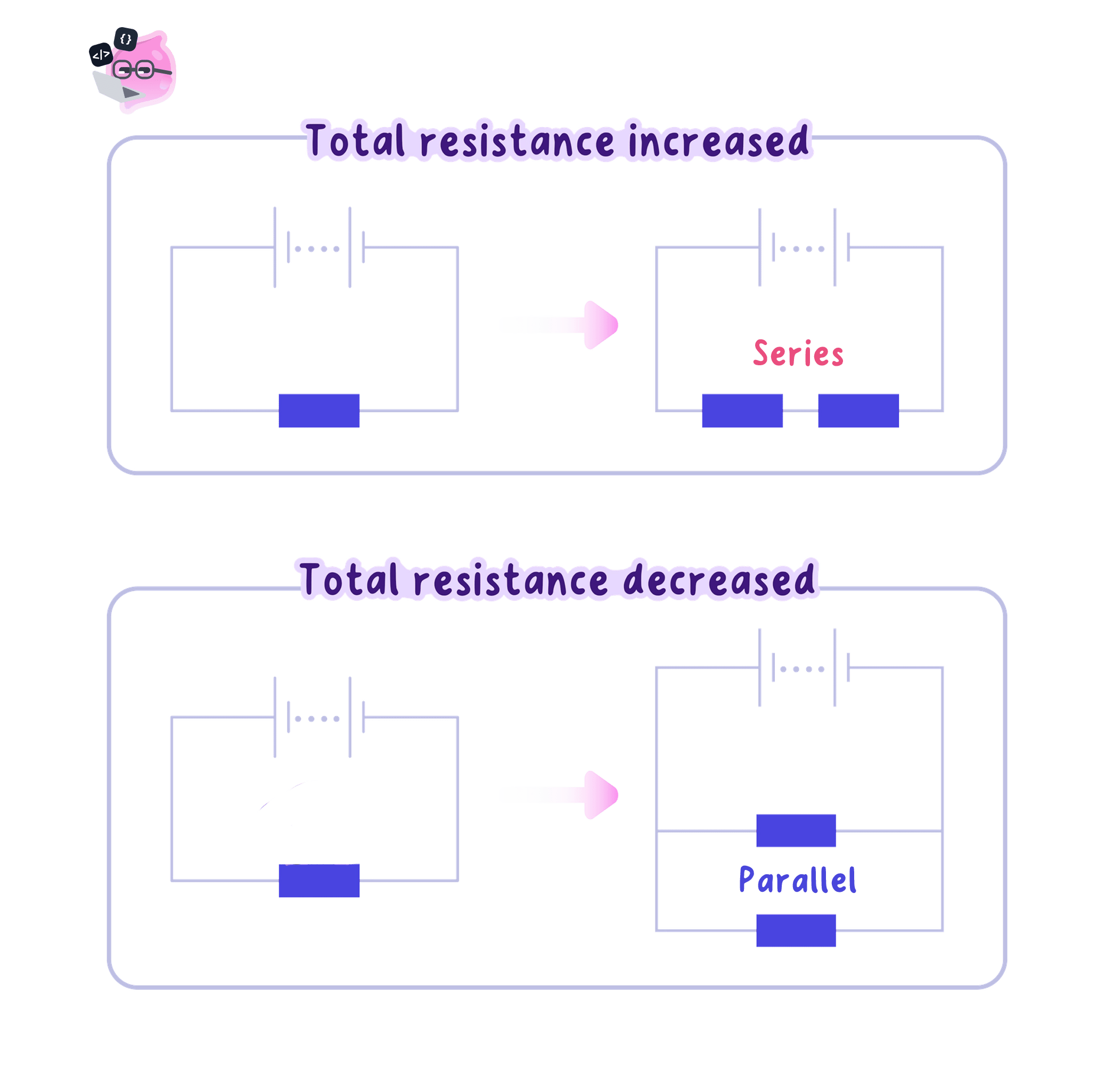
- The oppositions therefore add, and the total resistance of resistors in series is Rtotal=R1+R2+…R_{\text{total}}=R_{1}+R_{2}+\dotsRtotal=R1+R2+… for any number of them in the loop.
- The total resistance of a series combination is always larger than the largest single resistance within it, because the charge cannot avoid any of them.
- Resistors of 4.0 Ω4.0\ \Omega4.0 Ω and 6.0 Ω6.0\ \Omega6.0 Ω in series give Rtotal=4.0+6.0=10.0 ΩR_{\text{total}}=4.0+6.0=10.0\ \OmegaRtotal=4.0+6.0=10.0 Ω.
- Adding a further resistor in series always raises the total resistance, and no series arrangement can lower it.
- Since the supply potential difference has not changed, I=VRtotalI=\dfrac{V}{R_{\text{total}}}I=RtotalV shows that the current drawn from the supply falls whenever the total resistance rises.
- That smaller current is the same at every point in the single loop, so every component in the series circuit now carries less current than before.
Total resistance in series
- Three resistors of 12 Ω12\ \Omega12 Ω, 18 Ω18\ \Omega18 Ω and 20 Ω20\ \Omega20 Ω are connected in series across a 12 V12\ \text{V}12 V supply.
- The equation for a series combination is Rtotal=R1+R2+R3R_{\text{total}}=R_{1}+R_{2}+R_{3}Rtotal=R1+R2+R3.
- Substitution gives Rtotal=12+18+20=50 ΩR_{\text{total}}=12+18+20=50\ \OmegaRtotal=12+18+20=50 Ω.
- The current follows from I=VRtotalI=\dfrac{V}{R_{\text{total}}}I=RtotalV, so I=1250I=\dfrac{12}{50}I=5012.
- The current drawn from the supply is 0.24 A0.24\ \text{A}0.24 A, and the same 0.24 A0.24\ \text{A}0.24 A passes through each of the three resistors.
Resistance in parallel
- A parallel arrangement gives the charge more than one route, so it no longer has to pass through every resistor.
- Connecting a second branch across the supply gives the charge an extra path while leaving the current in the first branch unchanged, so the total current taken from the supply increases.
- A larger total current for the same supply potential difference can only mean a smaller total resistance, since Rtotal=VItotalR_{\text{total}}=\dfrac{V}{I_{\text{total}}}Rtotal=ItotalV.
- The total resistance of a parallel combination is therefore always smaller than the resistance of the smallest single resistor in it, not somewhere between the values.
- Two identical 10 Ω10\ \Omega10 Ω resistors in parallel across a 10 V10\ \text{V}10 V supply each carry 1.0 A1.0\ \text{A}1.0 A, giving Itotal=2.0 AI_{\text{total}}=2.0\ \text{A}Itotal=2.0 A and Rtotal=102.0=5.0 ΩR_{\text{total}}=\dfrac{10}{2.0}=5.0\ \OmegaRtotal=2.010=5.0 Ω, which is half the resistance of one of them alone.
- A 10 Ω10\ \Omega10 Ω resistor and a 40 Ω40\ \Omega40 Ω resistor in parallel across that same 10 V10\ \text{V}10 V supply carry 1.0 A1.0\ \text{A}1.0 A and 0.25 A0.25\ \text{A}0.25 A, so Itotal=1.25 AI_{\text{total}}=1.25\ \text{A}Itotal=1.25 A and Rtotal=101.25=8.0 ΩR_{\text{total}}=\dfrac{10}{1.25}=8.0\ \OmegaRtotal=1.2510=8.0 Ω, below the smaller of the two values.
- The qualitative argument carries the marks on its own: an extra branch is an extra path for charge, so the combination opposes the flow of charge less than any single branch does.
- Do not add resistances that are in parallel, because Rtotal=R1+R2R_{\text{total}}=R_{1}+R_{2}Rtotal=R1+R2 applies only to a series arrangement.
- Do not expect the total resistance of a parallel pair to lie between the two values, since it always falls below the smaller of them.
- Do not claim the current in an existing parallel branch drops when a new branch is added, as that branch still has the full supply potential difference across it.
- Do not use the total resistance to find a single branch current, because a branch current depends only on that branch's own resistance.
Changing the circuit
- Adding a resistor in series raises the total resistance, so the current falls at every point in that loop.
- Removing a resistor from a series loop lowers the total resistance, so the current rises at every point in that loop.
- Adding a branch in parallel lowers the total resistance, so the total current drawn from the supply rises.
- Removing a parallel branch raises the total resistance and lowers the total current, while every remaining branch carries exactly the current it carried before.
- A switch in series that opens makes the resistance of the loop effectively infinite, so the current everywhere in that loop falls to zero.
- A wire joined straight across a resistor offers a path of almost no resistance, so nearly all of the current takes the wire and the total resistance of the circuit drops sharply.
Series and parallel answers
- Quote Rtotal=R1+R2+…R_{\text{total}}=R_{1}+R_{2}+\dotsRtotal=R1+R2+… before adding anything, and say that it applies because the resistors are in series.
- For a parallel combination, state that the total resistance is less than the smallest branch resistance and give the extra-path reason.
- Find a branch current from I=VRI=\dfrac{V}{R}I=RV using that branch's own resistance together with the supply potential difference.
- Name both the change and its effect, such as that a third lamp in series raises the total resistance and so lowers the current, making every lamp dimmer.
- Convert kilohms into ohms before adding, so 1.2 kΩ1.2\ \text{k}\Omega1.2 kΩ in series with 800 Ω800\ \Omega800 Ω gives 2000 Ω2000\ \Omega2000 Ω.
Lamp brightness
- How brightly a lamp glows depends on the current through it and the potential difference across it, so anything that changes the total resistance changes the brightness.
- Two matched lamps in series across a 6 V6\ \text{V}6 V supply give a total resistance of twice one lamp, so the current is about half what a single lamp on its own would take.
- Each lamp in that series pair also has only about 3 V3\ \text{V}3 V across it instead of the full 6 V6\ \text{V}6 V, so the two glow dimly and equally.
- The same two lamps reconnected in parallel across that 6 V6\ \text{V}6 V supply each have the whole 6 V6\ \text{V}6 V across them, and each carries the current that a single lamp would take.
- Identical lamps are therefore brighter in parallel than in series for the same supply, and the parallel arrangement draws about twice the total current because its total resistance is about half that of one lamp.
Testing series and parallel circuits
- Aim: to test how current and potential difference behave in series and in parallel circuits built from the same two matched filament lamps.
- Apparatus: a low-voltage d.c. supply or a battery of cells, two matched filament lamps in holders, a fixed resistor, an ammeter, a voltmeter, a switch and connecting leads.
- Variables: the circuit arrangement, series or parallel, is the independent variable; the ammeter and voltmeter readings are the dependent variables; the same two lamps, the same supply setting and the same leads are kept the same throughout.
- Method, set-up:
- Draw the circuit diagram first, then build a single series loop containing the supply, the switch, the ammeter and both lamps.
- Set the supply to a low value such as 6 V6\ \text{V}6 V and push every connection home firmly, leaving the switch open.
- Have the circuit checked before the supply is switched on.
- Method, the series circuit:
- Close the switch briefly with the ammeter between the supply and the first lamp, and record the reading.
- Open the switch, move the ammeter to between the two lamps, close the switch again and record the current at that position.
- Repeat with the ammeter between the second lamp and the supply, so the current has been measured at three positions in the loop.
- Connect the voltmeter across the first lamp and record V1V_{1}V1, then across the second lamp for V2V_{2}V2, then across the supply terminals for VsupplyV_{\text{supply}}Vsupply.
- Note how brightly each lamp glows, then repeat every reading at least twice and take a mean.
- Method, the parallel circuit:
- Switch off and rebuild the circuit with the same two lamps on separate branches connected across the supply.
- Put the ammeter in the main branch, between the supply and the first junction, and record ItotalI_{\text{total}}Itotal.
- Move the ammeter into each branch in turn and record I1I_{1}I1 and I2I_{2}I2.
- Connect the voltmeter across each branch and then across the supply, and note the brightness of the lamps again.
- Results: in series the current is the same at all three positions and the lamp potential differences add to the supply value, V1+V2=VsupplyV_{1}+V_{2}=V_{\text{supply}}V1+V2=Vsupply; in parallel each branch has the full supply potential difference across it and the branch currents add, I1+I2=ItotalI_{1}+I_{2}=I_{\text{total}}I1+I2=Itotal.
- Maths: find each lamp's resistance from R=VIR=\dfrac{V}{I}R=IV, add the series values with Rtotal=R1+R2R_{\text{total}}=R_{1}+R_{2}Rtotal=R1+R2, then work out the parallel total from Rtotal=VsupplyItotalR_{\text{total}}=\dfrac{V_{\text{supply}}}{I_{\text{total}}}Rtotal=ItotalVsupply and check that it comes out below the resistance of either lamp on its own.
- Watch out: the matched lamps are visibly brighter in parallel than in series for the same supply, because the parallel total resistance is lower and each lamp then has the whole supply potential difference across it. A lamp's resistance rises as its filament heats, so readings taken while it is still warming will drift.
- Meter resolution, a zero error on either meter, loose contacts and the internal resistance of the supply all keep the readings from adding up exactly.
- Use digital meters on a suitable range, secure every contact, repeat each reading and open the switch between readings so the lamps do not sit and heat up.
- Safety: use a low-voltage supply only, switch off before changing any connection, avoid short circuits across the supply and do not touch a lamp or resistor that has been carrying current.
- State the equation for the total resistance of resistors in series and give the unit.
- Calculate the total resistance of 15 Ω15\ \Omega15 Ω, 25 Ω25\ \Omega25 Ω and 30 Ω30\ \Omega30 Ω in series, then the current drawn from a 14 V14\ \text{V}14 V supply.
- Explain why the total resistance of two resistors in parallel is less than the smaller of the two.
- State what happens to the total current when one parallel branch is disconnected, and why.
- Explain why two matched lamps are brighter in parallel than in series across the same supply.
10.2.4 I–V characteristics of components
Current-potential difference graphs
Current-potential difference graph
A current-potential difference graph is a plot of the current through a component against the potential difference across it, used to show how its resistance behaves.
Ohmic conductor
An ohmic conductor is a component whose resistance stays constant, so the current through it is directly proportional to the potential difference across it.
- A current-potential difference graph is built up by changing the potential difference across one component in steps and recording the current through it at each step.
- The current goes on the vertical axis and the potential difference on the horizontal axis, so the finished graph is a picture of how that one component behaves.
- Reversing the supply gives negative values of both quantities, so a full characteristic runs through the origin and into the third quadrant as well as the first.
- A steeper plot at a given potential difference means a larger current, and a larger current for the same potential difference means a smaller resistance, since R=VIR=\dfrac{V}{I}R=IV.
- An ohmic conductor gives a straight line through the origin, and its resistance works out the same at every point along that line.
- Any component whose graph curves is non-ohmic, because R=VIR=\dfrac{V}{I}R=IV then gives a different value at different points on the graph.
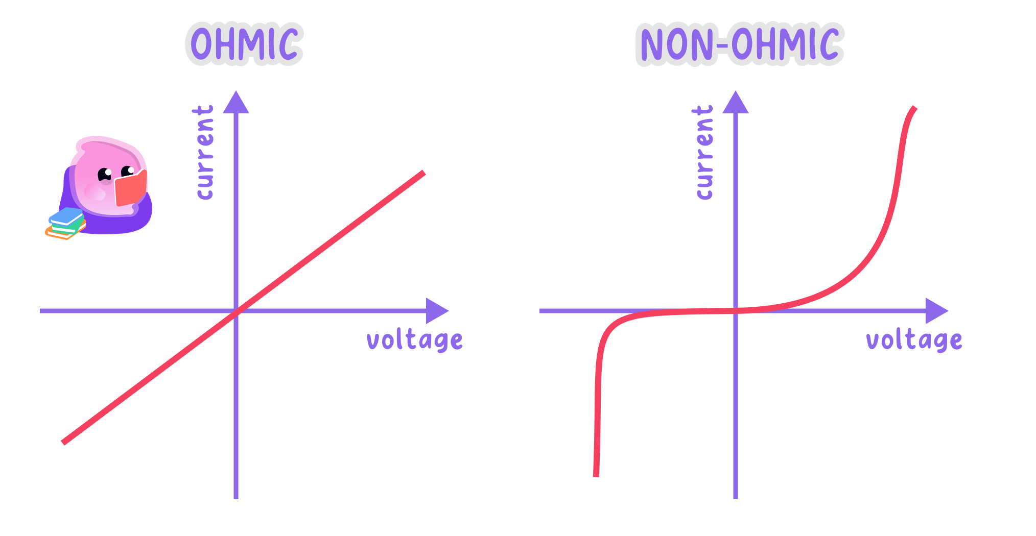
The shape of a current-potential difference graph shows whether a component's resistance stays constant, so only a straight line through the origin identifies an ohmic conductor.
The fixed resistor
- A fixed resistor held at constant temperature is an ohmic conductor, so its graph is a straight line passing through the origin.
- The line carries straight on into the negative region, because a resistor behaves in exactly the same way whichever direction the current takes.
- Current is directly proportional to potential difference for this component, so doubling the potential difference doubles the current and halving it halves the current.
- The resistance at any point on the graph is R=VIR=\dfrac{V}{I}R=IV, and every point on the same straight line returns the same value.
- The points (2.0 V, 0.10 A)(2.0\ \text{V},\ 0.10\ \text{A})(2.0 V, 0.10 A) and (6.0 V, 0.30 A)(6.0\ \text{V},\ 0.30\ \text{A})(6.0 V, 0.30 A) both give R=20 ΩR=20\ \OmegaR=20 Ω, which is what a constant resistance looks like on a graph.
- If the current is allowed to grow large enough to warm the resistor, its resistance rises and the line starts to bend, so readings are taken quickly at low current with the switch opened in between.
Resistance from a straight line
- A straight line through the origin passes through the point where the potential difference is 4.0 V4.0\ \text{V}4.0 V and the current is 0.16 A0.16\ \text{A}0.16 A.
- The resistance at a point on a graph is given by R=VIR=\dfrac{V}{I}R=IV.
- Substitution gives R=4.00.16R=\dfrac{4.0}{0.16}R=0.164.0.
- The resistance is R=25 ΩR=25\ \OmegaR=25 Ω.
- The point (8.0 V, 0.32 A)(8.0\ \text{V},\ 0.32\ \text{A})(8.0 V, 0.32 A) on the same line also gives 25 Ω25\ \Omega25 Ω, which confirms that the component is an ohmic conductor.
The filament lamp
Filament lamp
A filament lamp is a lamp that emits light because the current heats a thin coiled metal wire until it glows.
- A filament lamp gives a curve through the origin whose gradient decreases as the potential difference rises, so the plot flattens off towards each end.
- A larger potential difference drives a larger current, so more electrons pass through the thin metal filament every second.
- Those electrons collide more often with the vibrating positive ions of the filament's lattice, and each collision transfers energy from an electron to an ion.
- The ions therefore vibrate more strongly, so the internal energy and the temperature of the filament rise, reaching well over 1000 ∘C1000\,^{\circ}\text{C}1000∘C in a lamp that is glowing.
- Ions vibrating through larger distances get in the way of the drifting electrons more often, so collisions become still more frequent and the resistance of the filament increases.
- Because the resistance climbs as the lamp heats, each extra volt produces less extra current than the volt before it, and that is exactly why the curve flattens.
- The curve has the same shape on both sides of the origin, because the heating of the filament does not depend on which way the current passes through it.
Resistance of a hot filament
- A filament lamp characteristic passes through the points (2.0 V, 0.25 A)(2.0\ \text{V},\ 0.25\ \text{A})(2.0 V, 0.25 A) and (8.0 V, 0.40 A)(8.0\ \text{V},\ 0.40\ \text{A})(8.0 V, 0.40 A).
- The resistance at a point comes from R=VIR=\dfrac{V}{I}R=IV, using the coordinates of the point and not the gradient of the curve.
- At the first point, R=2.00.25=8.0 ΩR=\dfrac{2.0}{0.25}=8.0\ \OmegaR=0.252.0=8.0 Ω.
- At the second point, R=8.00.40=20 ΩR=\dfrac{8.0}{0.40}=20\ \OmegaR=0.408.0=20 Ω.
- The resistance has risen from 8.0 Ω8.0\ \Omega8.0 Ω to 20 Ω20\ \Omega20 Ω because the filament is far hotter at the larger potential difference.
The diode
Diode
A diode is a component that allows current to flow through it in one direction only.
- A diode allows current to pass in one direction only, the forward direction shown by the arrowhead in its circuit symbol.
- Connected in reverse, a diode has an extremely high resistance, so its graph lies along the horizontal axis with a current of practically zero.
- Connected forwards, almost no current passes until the potential difference reaches about 0.6 V0.6\ \text{V}0.6 V, so the graph stays close to the axis over that first stretch.
- Above about 0.6 V0.6\ \text{V}0.6 V the current rises very steeply, which means the resistance of the diode has dropped sharply.
- The characteristic is neither a straight line nor symmetrical about the origin, so a diode is not an ohmic conductor.
- A light-emitting diode has the same shaped characteristic and gives out light once it conducts, and a diode placed in series protects a component that a reversed supply would damage.
- Do not take the resistance of a filament lamp or a diode from the gradient of the curve, because the gradient of a curve changes from point to point.
- Do not call a filament lamp ohmic just because its graph passes through the origin, since an ohmic conductor has to give a straight line as well.
- Do not write that the resistance of a lamp falls as it grows brighter, because the resistance rises as the filament gets hotter.
- Do not sketch a diode characteristic rising straight from the origin, as the forward current stays near zero until about 0.6 V0.6\ \text{V}0.6 V.
Reading a graph
- Identify the axes first, then decide whether the plot is a straight line, a smooth curve, or a flat section followed by a sudden rise.
- A straight line through the origin belongs to a fixed resistor at constant temperature, a curve flattening at both ends belongs to a filament lamp, and a flat section with a steep rise in one direction only belongs to a diode.
- Read a pair of coordinates off the axes and use R=VIR=\dfrac{V}{I}R=IV to get the resistance at that point, always stating which point was used.
- For a straight line only, the gradient of the graph equals 1R\dfrac{1}{R}R1, so a steeper straight line means a smaller resistance.
Answering graph questions
- Name the component and describe the shape before explaining anything, using wording such as a curve with a decreasing gradient.
- Quote R=VIR=\dfrac{V}{I}R=IV and give the coordinates used, so the source of each substituted value is visible.
- Give the full chain for a filament lamp: larger current, more collisions with the vibrating ions, higher temperature, higher resistance.
- Use directly proportional only for the fixed resistor's straight line through the origin.
- State that a diode conducts in one direction only, and quote the turn-on value of about 0.6 V0.6\ \text{V}0.6 V when the graph shows it.
Measuring current and potential difference
- Aim: to find how the current depends on the potential difference for a fixed resistor and then for a filament lamp, and to calculate the resistance of each from the readings.
- Apparatus: a low-voltage d.c. power supply or a battery of cells, a fixed resistor, a filament lamp in a holder, a variable resistor, an ammeter, a voltmeter, a switch, connecting leads and a reversing switch if a full characteristic is wanted.
- Variables: the potential difference across the test component is the independent variable, the current through it is the dependent variable, and the component on test, the supply and the surroundings are kept the same across one set of readings.
- Method, set-up:
- Draw the circuit diagram first: the supply, the switch, the ammeter, the variable resistor and the test component all in one series loop.
- Connect the voltmeter in parallel across the test component alone, so it reads the potential difference across that component and nothing else.
- Check that both meters are connected the right way round for a d.c. supply, and set the variable resistor to its largest resistance.
- Have the circuit checked before switching on, and leave the switch open until then.
- Method, the fixed resistor:
- Close the switch briefly, read the ammeter and the voltmeter at the same instant, record both values, then open the switch again.
- Move the variable resistor slider a little to change the potential difference and take the next pair of readings the same way.
- Collect at least six pairs of readings spread across the available range, opening the switch between each pair so the resistor does not warm up.
- Reverse the connections at the supply, or throw the reversing switch, and repeat to collect negative pairs of readings for the other half of the characteristic.
- Method, the filament lamp:
- Switch off, take the fixed resistor out and put the filament lamp in its place, leaving the rest of the circuit untouched.
- Repeat the whole set of readings, waiting a few seconds after each pair so the filament cools back towards a steady temperature.
- Take extra pairs of readings at low potential difference, where the curve bends most sharply and a gap in the data is most obvious.
- Results: the fixed resistor gives a straight line through the origin, so its resistance is constant; the filament lamp gives a curve whose gradient decreases as the potential difference rises, because the resistance of the filament increases as it gets hotter.
- Maths: calculate the resistance at chosen points from R=VIR=\dfrac{V}{I}R=IV using coordinates read off the graph, plot current on the vertical axis against potential difference on the horizontal axis, and draw one smooth line or curve of best fit through both the positive and the negative readings.
- Watch out: read the ammeter and the voltmeter at the same moment, because both readings drift as soon as the component starts to warm. Take the resistance of the lamp from a pair of coordinates rather than from the gradient of the curve.
- Meter resolution, a zero error on either meter, loose contacts and the internal resistance of the supply all limit how close the readings come to the true values.
- Use digital meters on a suitable range, push every connection home, repeat each pair of readings and keep the switch open in between so heating is limited.
- Safety: use a low-voltage supply only, switch off before changing any connection, avoid short circuits across the supply and do not touch the lamp or the resistor after current has passed through it.
- State what a graph must look like for a component to be an ohmic conductor.
- A straight line through the origin passes through (3.0 V, 0.12 A)(3.0\ \text{V},\ 0.12\ \text{A})(3.0 V, 0.12 A). Calculate the resistance.
- Explain in full why the resistance of a filament lamp increases as the potential difference across it rises.
- Describe the shape of a diode characteristic in both the forward and the reverse direction.
- Explain why the resistance of a lamp at a point is found from coordinates and not from the gradient of the curve.
10.2.5 LDRs and thermistors
The light-dependent resistor
Light-dependent resistor
A light-dependent resistor is a component whose resistance decreases as the intensity of the light falling on it increases.
- A light-dependent resistor is made from a semiconducting material whose resistance depends on the light falling on its surface.
- In bright light the resistance of a typical light-dependent resistor is only a few hundred ohms, while in complete darkness it can rise above a million ohms.
- Light arriving at the semiconductor frees more of its electrons to move, so more charge carriers become available and the material opposes the flow of charge less.
- As the light intensity rises the resistance falls, and as the light intensity falls the resistance rises again.
- The graph of resistance against light intensity is a curve, falling steeply at low intensity and levelling off at high intensity, so the relationship is not linear.
- Because its resistance changes with the conditions rather than staying fixed, a light-dependent resistor is not an ohmic component.
Current through a light sensor
- A light-dependent resistor is connected across a 6.0 V6.0\ \text{V}6.0 V supply, and in bright light its resistance is 500 Ω500\ \Omega500 Ω.
- The current is found from I=VRI=\dfrac{V}{R}I=RV.
- In bright light, I=6.0500=0.012 AI=\dfrac{6.0}{500}=0.012\ \text{A}I=5006.0=0.012 A, which is 12 mA12\ \text{mA}12 mA.
- With the lamp switched off the resistance rises to 200 kΩ200\ \text{k}\Omega200 kΩ, which must be converted to 200 000 Ω200\,000\ \Omega200000 Ω before substituting.
- In the dark, I=6.0200 000=0.000030 AI=\dfrac{6.0}{200\,000}=0.000030\ \text{A}I=2000006.0=0.000030 A, which is 30 μA30\ \mu\text{A}30 μA, so the current has fallen to one four-hundredth of its bright-light value.
The thermistor
Thermistor
A thermistor is a component whose resistance decreases as its temperature increases.
- A thermistor is made from a semiconductor whose resistance depends strongly on its own temperature.
- In the type used in school circuits the resistance falls as the temperature rises, which is the opposite of what happens in a metal wire.
- Heating the semiconductor frees more of its electrons to move, so more charge carriers become available and the resistance drops.
- A laboratory thermistor might fall from about 10 kΩ10\ \text{k}\Omega10 kΩ at 10 ∘C10\,^{\circ}\text{C}10∘C to a few hundred ohms at 80 ∘C80\,^{\circ}\text{C}80∘C.
- The graph of resistance against temperature is a curve, falling steeply at low temperature and flattening out at high temperature, so the change is not linear.
- A thermistor is therefore not an ohmic component either, since R=VIR=\dfrac{V}{I}R=IV gives a different value at every temperature.
Current through a thermistor
- A thermistor is connected in series with a fixed resistor of resistance 1000 Ω1000\ \Omega1000 Ω across a 9.0 V9.0\ \text{V}9.0 V supply, and at room temperature the thermistor has a resistance of 8000 Ω8000\ \Omega8000 Ω.
- The resistance of the whole loop is 8000+1000=9000 Ω8000+1000=9000\ \Omega8000+1000=9000 Ω.
- The current is I=9.09000=0.0010 AI=\dfrac{9.0}{9000}=0.0010\ \text{A}I=90009.0=0.0010 A, which is 1.0 mA1.0\ \text{mA}1.0 mA.
- Warming the thermistor brings its resistance down to 500 Ω500\ \Omega500 Ω, so the loop resistance becomes 500+1000=1500 Ω500+1000=1500\ \Omega500+1000=1500 Ω.
- The current rises to I=9.01500=0.0060 AI=\dfrac{9.0}{1500}=0.0060\ \text{A}I=15009.0=0.0060 A, six times the earlier value, and the potential difference across the fixed resistor rises with it.
Sensing circuits
Sensing circuit
A sensing circuit is a circuit that uses a component whose resistance changes with a physical condition so that the circuit responds automatically to that condition.
- A sensing circuit places a light-dependent resistor or a thermistor in series with a fixed resistor across a supply, and takes its output from across one of the two.
- When the sensor's resistance changes, the resistance of the whole loop changes with it, so the current in the loop changes as well.
- The potential difference across the fixed resistor then changes too, because V=IRV=IRV=IR with a fixed value of RRR means that potential difference follows the current.
- Whatever share of the supply potential difference is not across the fixed resistor is across the sensor, so the two shares always move in opposite directions.
- An electronic switch or a relay connected to the output turns a device on or off once the potential difference reaches a set value.
- The full chain for an outdoor lamp at dusk runs like this: the light level falls, the light-dependent resistor's resistance rises, the current in the loop falls, the potential difference across the fixed resistor falls while the potential difference across the sensor rises, and the switch turns the lamp on.
A sensing circuit turns a change in light or temperature into a change in resistance, which becomes a change in current and therefore a change in potential difference that an electronic switch can act on.
Where they are used
- Street lighting uses a light-dependent resistor to switch lamps on automatically at dusk and off again at dawn, so no energy is spent lighting an already bright street.
- Outdoor security lighting uses the same arrangement, so a lamp responds to movement only once it is dark.
- A camera sets its exposure and a phone dims its screen using a light sensor of the same kind.
- A room thermostat uses a thermistor, so the heating switches off as the room warms and comes back on as it cools.
- An oven, a fridge and a freezer each use a thermistor to hold the temperature inside within a set range.
- A fire alarm uses a thermistor to detect a rapid temperature rise, and an engine coolant sensor uses one to warn the driver that the engine is overheating.
- Do not say that a light-dependent resistor's resistance rises in bright light, because more light frees more charge carriers and so lowers the resistance.
- Do not treat the resistance of a thermistor as rising with temperature, since that is the behaviour of a metal wire and not of a semiconductor.
- Do not describe either resistance graph as a straight line, as both are curves that are steep at one end and flat at the other.
- Do not stop an explanation at the change in resistance, because the remaining marks sit on the change in current and the change in potential difference.
Investigating the components
- The light-dependent resistor is connected in series with a cell, a switch and an ammeter, with a voltmeter across the sensor itself.
- A lamp is set up a measured distance away on the bench and the room is darkened, so that only the lamp lights the sensor.
- The lamp is then moved to a series of measured distances, or a light meter records the intensity at each setting, and both meters are read at every setting.
- The resistance at each light level comes from R=VIR=\dfrac{V}{I}R=IV, and resistance is plotted against light intensity to give the falling curve.
- For the thermistor, the sensor is held in a water bath next to a thermometer and the water is heated in steps of about 10 ∘C10\,^{\circ}\text{C}10∘C.
- The water is stirred so the thermistor and the thermometer are at the same temperature, then both meters are read at each temperature and R=VIR=\dfrac{V}{I}R=IV is used again.
- The supply setting is kept the same throughout and each pair of readings is taken quickly, so the current does not warm the sensor and change the very quantity being measured.
Explaining sensor circuits
- State the change in the condition first, such as the light level falling or the temperature rising.
- Give the change in the sensor's resistance next, saying clearly whether it rises or falls.
- Follow that with the change in the current, quoting I=VRI=\dfrac{V}{R}I=RV as the reason.
- Then give the change in the potential difference across the fixed resistor, quoting V=IRV=IRV=IR.
- Finish by naming the device that responds and whether it switches on or off, because the last mark sits on the effect.
- State what happens to the resistance of a light-dependent resistor as the light intensity rises, and give the reason.
- State what happens to the resistance of a thermistor as its temperature rises, and give the reason.
- Describe the shape of the resistance against temperature curve for a thermistor.
- Explain why neither a light-dependent resistor nor a thermistor is an ohmic component.
- Describe the full chain of changes in a street-lighting sensing circuit as darkness falls.
