5.1.1 Reflection, refraction and total internal reflection
Reflection: angles are measured from the normal
Reflection
The change in direction of a wave at a boundary so that it remains in the original medium.
- A ray is a straight line with an arrow that shows the direction in which light travels.
- The normal is an imaginary line drawn at 90∘90^\circ90∘ to the surface at the point where the ray meets the boundary.
- The angle of incidence, iii, is the angle between the incident ray and the normal.
- The angle of reflection, rrr, is the angle between the reflected ray and the normal.
- The law of reflection is i=ri=ri=r, so the incident ray and reflected ray make equal angles with the normal.
- A ray travelling along the normal has i=0∘i=0^\circi=0∘ and is reflected back along the same path.
Applying the law of reflection
- A ray strikes a plane mirror at 37∘37^\circ37∘ to the normal.
- The law of reflection gives r=i=37∘r=i=37^\circr=i=37∘.
- The angle between the incident and reflected rays is 37∘+37∘=74∘37^\circ+37^\circ=74^\circ37∘+37∘=74∘.
Refraction: speed changes at a boundary
Refraction
The change in direction of a wave caused by a change in speed as it passes from one medium into another.
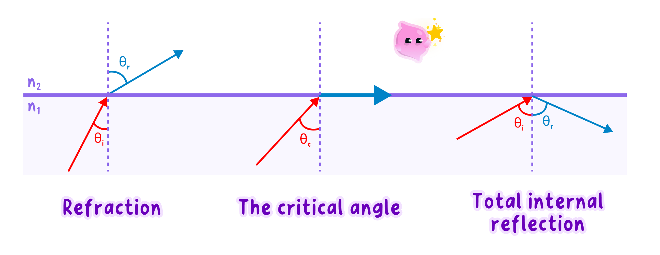
- When light enters a more optically dense medium, such as glass from air, it slows down and bends towards the normal.
- When light enters a less optically dense medium, such as air from glass, it speeds up and bends away from the normal.
- Light travelling along the normal changes speed but does not change direction because its angle of incidence is 0∘0^\circ0∘.
- The frequency of the light is fixed by the source and does not change at the boundary.
- Since v=fλv=f\lambdav=fλ, a lower speed at unchanged frequency means a shorter wavelength in the more optically dense medium.
- At a glass boundary, part of the light can be refracted and part can be reflected.
Investigating refraction in a rectangular block
- Apparatus: ray box with a single slit or an approved low-power classroom laser, rectangular glass or acrylic block, plain paper, pencil, ruler, protractor and power supply.
- Independent variable: angle of incidence.
- Dependent variable: angle of refraction.
- Control variables: block material, light colour, entry face, entry point and angle-measuring method.
- Method:
- Place the block on the paper, trace its outline and draw a normal at the chosen entry point.
- Direct one narrow ray at the entry point and mark two points on the incident ray and two points on the emergent ray.
- Remove the block, join the marked points with a ruler and connect the entry and exit points to reconstruct the ray inside the block.
- Measure the angles of incidence and refraction from the normal, not from the block surface.
- Repeat for at least five angles of incidence, repeat each reading and calculate a mean angle of refraction.
- Record the results in a table and plot angle of refraction against angle of incidence if required.
- Expected pattern: light bends towards the normal on entering the block and away from the normal on leaving it, while the emergent ray is parallel to the incident ray because the block faces are parallel.
- Safety: never look into the beam or direct it at another person, keep leads tidy and avoid touching a hot ray-box lamp.
- Uncertainty: thick pencil lines, a broad ray, parallax, movement of the block and incorrect protractor alignment increase uncertainty.
- Improvements: use a narrow beam and sharp pencil, space ray marks widely apart, keep the block on its outline, measure from the centre of each ray and repeat readings.
Total internal reflection needs two conditions
Total internal reflection
The complete reflection of light back into an optically denser medium when it meets a boundary above the critical angle.
- The critical angle, ccc, is the angle of incidence in the optically denser medium that produces an angle of refraction of 90∘90^\circ90∘.
- At i<ci<ci<c, some light leaves the denser medium by refraction and some can be reflected.
- At i=ci=ci=c, the refracted ray travels along the boundary because its angle to the normal is 90∘90^\circ90∘.
- At i>ci>ci>c, total internal reflection occurs and no refracted ray leaves the medium.
- Total internal reflection can occur only when light travels from a more optically dense medium to a less optically dense medium, such as glass to air.
- Optical fibres use repeated total internal reflection to guide light along the transparent core, including around gentle bends.
- Do not measure an angle from the surface; every incidence, reflection and refraction angle is measured from the normal.
- Do not state that light always bends at a boundary; a ray along the normal changes speed without changing direction.
- Do not claim that a large angle alone causes total internal reflection; the ray must also travel from a more optically dense medium to a less optically dense medium.
Drawing ray diagrams
- Draw the boundary and a dashed normal at 90∘90^\circ90∘ before adding the rays.
- Put arrowheads on every ray and show whether the ray is travelling towards or away from the boundary.
- For an explanation of refraction, link the change in speed to the change in direction and state whether the ray bends towards or away from the normal.
- For total internal reflection, state both required conditions and compare iii with ccc.
- State the law of reflection and identify the line from which both angles are measured.
- Explain why light bends towards the normal when it enters glass from air.
- State what happens to speed, frequency and wavelength when light enters glass from air.
- Define the critical angle.
- State both conditions required for total internal reflection.
5.1.2 Specular and diffuse reflection
Surface roughness controls reflected-ray directions
Specular reflection
Reflection from a smooth surface in which parallel incident rays remain parallel after reflection.
Diffuse reflection
Reflection from a rough surface in which parallel incident rays are reflected in many directions.
- A smooth surface has normals pointing in almost the same direction at neighbouring points.
- Parallel rays therefore strike at the same angle of incidence and leave at the same angle of reflection.
- The reflected rays remain ordered, so a clear image can form in a mirror, still water or polished metal.
- Each ray obeys i=ri=ri=r.
- A rough surface has microscopic slopes, so the normal points in a different direction at each point.
- Each ray still obeys i=ri=ri=r relative to its own local normal, but the reflected rays travel in different directions.
- The scattered rays do not preserve the ordered pattern needed for a clear image.
- Paper, unpolished wood and a painted wall usually produce diffuse reflection.
Diffuse reflection makes objects visible from many positions
- A smooth surface directs most reflected light into a narrow range of directions, so glare or a bright reflected image may be seen from only certain positions.
- A rough surface sends reflected light towards observers in many positions, which is why writing on paper can be read from different angles.
- Diffuse reflection does not mean that light is absorbed; it means that the reflected light leaves in many directions.
Comparing two surfaces
- Parallel rays striking a plane mirror meet nearly parallel local normals.
- The rays reflect in parallel directions, so the mirror produces specular reflection and can form an image.
- The same rays striking matt paper meet differently oriented local normals.
- The rays obey i=ri=ri=r at each point but spread out, so the paper produces diffuse reflection and no clear image.
- Do not say that diffuse reflection breaks the law of reflection; each ray still obeys i=ri=ri=r at its point of incidence.
- Do not describe a visibly rough object only by its large-scale shape; the relevant roughness is on the scale of the light-reflecting surface.
- Do not confuse diffuse reflection with absorption.
Explaining the difference
- Compare the surfaces first: smooth for specular reflection and rough for diffuse reflection.
- Then compare the rays: parallel rays remain parallel after specular reflection but leave in many directions after diffuse reflection.
- State that the law of reflection applies to every individual ray in both cases.
- Define specular reflection.
- Define diffuse reflection.
- Explain why a rough surface sends reflected rays in different directions.
- State whether the law of reflection applies during diffuse reflection.
- Explain why matt paper can be viewed from many positions.
5.1.3 Colour of light: absorption and filters
Object colour depends on which wavelengths reach the eye
Absorption
The transfer of energy from electromagnetic radiation to a material when the radiation is taken in rather than reflected or transmitted.
- White light contains the visible wavelengths that the eye interprets as different colours.
- An opaque surface appears a particular colour because it reflects that colour or range of colours and absorbs most of the others.
- A red object in white light reflects red light and absorbs most other visible wavelengths.
- A white surface reflects most visible wavelengths, while a black surface absorbs most visible wavelengths.
- The observed colour depends on both the wavelengths in the incident light and the wavelengths the surface reflects.
- A red object illuminated only with blue light appears very dark because there is no red light to reflect and the blue light is mostly absorbed.
Filters transmit selected colours
Colour filter
A transparent material that transmits a selected wavelength or range of visible wavelengths and absorbs most other visible wavelengths.
- A red filter transmits red light and absorbs most other visible colours.
- A filter cannot create a missing colour; it can only transmit wavelengths already present in the incident light.
- White light passing through a blue filter appears blue because blue wavelengths are transmitted while most other wavelengths are absorbed.
- Red light incident on a blue filter produces little or no transmitted light because the blue filter absorbs the red light.
- Two filters in sequence transmit only wavelengths that both filters allow through.
Predicting the observed colour
- A green leaf reflects green light and absorbs most other visible wavelengths.
- Under red light, the leaf receives no green wavelength to reflect.
- It absorbs most of the red light, so it appears very dark.
- If viewed through a green filter under white light, green light from the leaf is transmitted and the leaf remains visible.
Use a wavelength pathway to explain colour
- First identify the wavelengths present in the light source.
- Then state which wavelengths the surface reflects and which it absorbs.
- If a filter is present, state which remaining wavelengths it transmits and which it absorbs.
- The colour reaching the eye is the wavelength that survives every stage.
- Do not say that an object contains or produces its colour; an opaque object appears coloured because of selective reflection and absorption.
- Do not say that a filter adds colour to light; a filter removes wavelengths by absorption and transmits selected wavelengths.
- Do not assume an object's colour is unchanged under coloured illumination.
Writing colour explanations
- Name the incident colour before describing the surface or filter.
- Use the precise verbs reflects, absorbs and transmits.
- Follow the light from source to surface, through any filter, and then to the eye.
- Explain why a red object appears red in white light.
- Explain why a white surface appears white.
- Define a colour filter.
- Predict the appearance of a blue object under red light and explain your answer.
- State what happens when red light reaches a blue filter.
5.1.4 Lenses: power, focal length and shape
Lens power increases as focal length decreases
Principal focus
The point on the principal axis at which rays parallel to the axis converge, or appear to diverge from, after passing through a lens.
Focal length
The distance from the optical centre of a lens to its principal focus.
- The principal axis is the straight line through the optical centre and both principal foci.
- The optical centre is the central point of a thin lens through which a ray passes without changing direction.
- The power of a lens measures how strongly it converges or diverges light.
- Lens power is calculated using P=1fP=\dfrac{1}{f}P=f1, where PPP is in dioptres, D\text{D}D, and fff is in metres, m\text{m}m.
- A shorter focal length gives a larger magnitude of power because the rays are bent more strongly.
- A converging lens has positive power, while a diverging lens has negative power.
Calculating lens power
- A converging lens has focal length 20 cm=0.20 m20\ \text{cm}=0.20\ \text{m}20 cm=0.20 m.
- Using P=1fP=\dfrac{1}{f}P=f1 gives P=10.20=+5.0 DP=\dfrac{1}{0.20}=+5.0\ \text{D}P=0.201=+5.0 D.
- A diverging lens with focal length −0.50 m-0.50\ \text{m}−0.50 m has power P=1−0.50=−2.0 DP=\dfrac{1}{-0.50}=-2.0\ \text{D}P=−0.501=−2.0 D.
Shape determines how strongly a lens bends light
Converging lens
A lens that is thicker at the centre than at the edges and refracts parallel rays towards a principal focus.
Diverging lens
A lens that is thinner at the centre than at the edges and refracts parallel rays so that they spread out as if they came from a principal focus.
- A more strongly curved converging lens changes the direction of rays more, so it has a shorter focal length and a larger positive power.
- A less strongly curved converging lens bends rays less, so it has a longer focal length and a smaller positive power.
- A more strongly curved diverging lens spreads rays more, so the magnitude of its negative power is larger and its focal length has a smaller magnitude.
- Lens material also affects refraction, but comparisons of shape assume the same transparent material.
Power must be compared using magnitude and sign
- The sign identifies the type of lens: positive for converging and negative for diverging.
- The magnitude, ∣P∣|P|∣P∣, identifies the strength of the lens.
- A lens of −6 D-6\ \text{D}−6 D is stronger than a lens of +2 D+2\ \text{D}+2 D because 6>26>26>2, although the lenses bend rays in opposite ways.
- Convert centimetres to metres before using P=1fP=\dfrac{1}{f}P=f1.
- Do not say that a larger focal length means a more powerful lens; power is inversely proportional to focal length.
- Do not ignore the sign of the power when identifying whether a lens converges or diverges light.
Power calculations
- Write P=1fP=\dfrac{1}{f}P=f1 and convert the focal length to metres before substitution.
- Include the unit D\text{D}D and use the sign to identify the lens type.
- When comparing lens strength, compare ∣P∣|P|∣P∣ rather than only the signed numerical values.
- Define focal length.
- State the equation linking lens power and focal length.
- Explain why a more strongly curved converging lens has greater power.
- State the sign of the power of a diverging lens.
- Calculate the power of a converging lens with focal length 0.25 m0.25\ \text{m}0.25 m.
5.1.5 Ray diagrams for converging and diverging lenses
Ray diagrams use three predictable rays
Ray diagram
A scale drawing that uses the paths of light rays to locate and describe an image.
Principal axis
The straight line through the optical centre of a lens and its two principal foci.
- Draw the lens, the principal axis, a principal focus on each side and an upright object before drawing rays.
- Use a ruler, place arrowheads on rays and draw at least two construction rays from the top of the object.
- The image is located where refracted rays meet, or where their backward extensions meet.
A converging lens bends parallel rays through the focus
- A ray parallel to the principal axis is refracted through the principal focus on the far side of a converging lens.
- A ray through the optical centre continues undeviated.
- A ray directed through the principal focus on the near side emerges parallel to the principal axis.
- Any two of these rays are sufficient to locate the image; the third ray checks the construction.
- When refracted rays actually meet, draw the image at their intersection.
Converging-lens construction
- Place the object beyond 2F2F2F on the left of a converging lens.
- Draw one ray parallel to the axis and refract it through the far focus.
- Draw a second ray through the optical centre without changing its direction.
- The rays meet between FFF and 2F2F2F on the far side, so the image is real, inverted and smaller than the object.
A diverging lens makes rays spread out
- A ray parallel to the principal axis is refracted so that it appears to have come from the principal focus on the same side as the object.
- Draw this refracted ray away from the axis, then extend it backwards with a dashed line through the near focus.
- A ray through the optical centre continues undeviated.
- The backward extensions meet on the same side as the object, between the lens and the near focus.
- A diverging lens therefore produces a virtual, upright and diminished image for a real object.
Diverging-lens construction
- Draw a ray from the object top parallel to the axis, then refract it away from the axis.
- Extend the refracted ray backwards through the near focus using a dashed line.
- Draw a second ray through the optical centre.
- The backward extension meets the central ray between the lens and near focus, which locates the virtual image.
Object position changes a converging-lens image
- With the object beyond 2F2F2F, the image forms between FFF and 2F2F2F and is real, inverted and diminished.
- With the object at 2F2F2F, the image forms at 2F2F2F and is real, inverted and the same size.
- With the object between FFF and 2F2F2F, the image forms beyond 2F2F2F and is real, inverted and magnified.
- With the object at FFF, emerging rays are parallel and the image is effectively at infinity.
- With the object between the lens and FFF, the emerging rays diverge and their backward extensions form a virtual, upright and magnified image on the object's side.
- Do not bend the ray that passes through the optical centre of a thin lens.
- Use solid lines for real light rays and dashed lines only for backward extensions used to locate a virtual image.
- Do not force rays to meet; extend them accurately and place the image where they intersect.
Constructing accurate diagrams
- Mark both foci at equal distances from the lens and keep the drawing to scale where distances are supplied.
- Start each construction ray at the top of the object.
- Use the intersection to state image position, then describe orientation and relative size.
- State the path of a ray parallel to the axis through a converging lens.
- State the path of a ray through the optical centre of a thin lens.
- Explain how to draw the refracted path of a parallel ray through a diverging lens.
- Describe the image formed by a converging lens when the object lies beyond 2F2F2F.
- Describe the image formed by a diverging lens.
5.1.6 Real and virtual images
Real images form where light rays meet
Real image
An image formed where light rays actually converge that can be projected onto a screen.
- A converging lens produces a real image when the object is farther from the lens than the focal length.
- The image forms on the opposite side of the lens from the object.
- A real image produced by a single converging lens is inverted.
- Its size depends on object position: it can be diminished, the same size or magnified.
- A camera sensor, cinema screen and the retina receive real images because light rays reach those surfaces.
Virtual images form where rays appear to meet
Virtual image
An image formed where diverging light rays appear to come from that cannot be projected onto a screen.
- A converging lens produces a virtual image when the object is between the lens and its principal focus.
- That image is upright, magnified and on the same side of the lens as the object.
- A diverging lens produces a virtual, upright and diminished image for every position of a real object.
- In a ray diagram, dashed backward extensions meet at the virtual image position, but no light travels along those extensions.
- A magnifying glass works by placing the object inside the focal length of a converging lens, so the eye receives diverging rays that appear to come from a larger upright image.
Classifying an image
- A lens forms an image on a white card placed behind the lens.
- Light rays must actually reach the card, so the image is real.
- When the object is moved inside the focal length, no sharp image can be caught on the card.
- Looking through the lens shows an upright enlarged image, so the new image is virtual.
Image descriptions use four properties
- State whether the image is real or virtual.
- State whether it is upright or inverted.
- Compare its size with the object using magnified, same size or diminished.
- State its position relative to the lens, object and principal focus where the diagram provides that information.
- A screen test distinguishes image type: a sharp image on a screen is real, while an image visible only by looking into the optical system is virtual.
- Do not define a virtual image as an image that cannot be seen; virtual images are visible to the eye but cannot be projected onto a screen.
- Do not assume every magnified image is virtual; a converging lens can form a magnified real image when the object lies between FFF and 2F2F2F.
- Do not draw dashed extensions as real rays.
Describing lens images
- Give all four properties requested by the diagram: type, orientation, relative size and position.
- Use the screen test when experimental evidence is described.
- Base the description on the ray intersection rather than on a memorised label alone.
- Define a real image.
- Define a virtual image.
- State the screen test that distinguishes real and virtual images.
- Describe the image formed by a converging lens when the object lies inside the focal length.
- Describe the image formed by a diverging lens.
