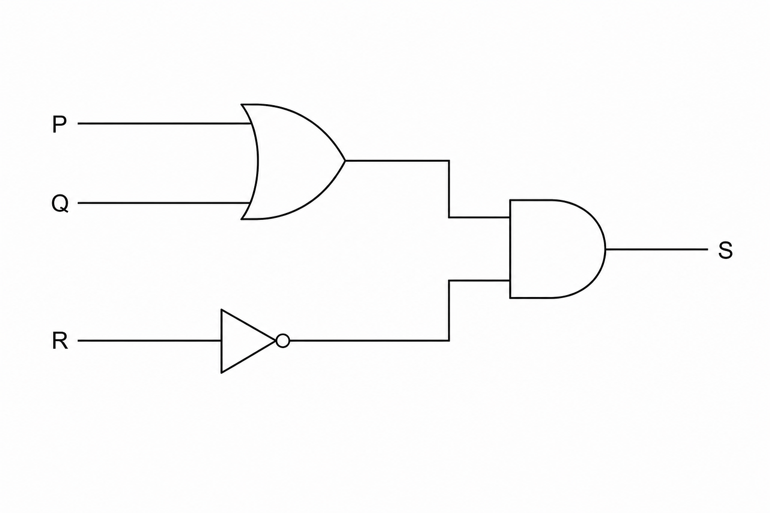
Figure 1 shows a logic circuit.
Write a Boolean expression that represents the logic circuit shown in Figure 1.
You must use correct Boolean operators (such as AND, OR, NOT or equivalent symbols like ⋅\cdot⋅, +++, blank‾\overline{\text{blank}}blank / ∧\wedge∧, ∨\vee∨, ¬\neg¬) in your expression.
Boolean logic Questions
Practise AQA GCSE Computer Science Boolean logic with exam-style questions for GCSE Computer Science. 83 questions, matched to the AQA GCSE Computer Science (8525) specification and written in Paper 1 and Paper 2 style. Every question includes a full worked solution and mark scheme, so you can see where marks are awarded rather than just whether you got the answer right.