Revision notes for Edexcel A Level Physics Electromagnetic induction. Open the guide for explanations and worked examples. Written against the Edexcel A Level Physics (9PH0) specification, so the content matches what's examinable rather than general Physics background.
Electromagnetic induction
What you'll learn
- Understand magnetic flux: how much magnetic field passes through a loop.
- Use Faraday’s law: how quickly changing flux produces an induced voltage.
- Use Lenz’s law: the direction rule for induced currents.
- Apply induction to moving conductors, generators and transformers.
The basic idea
Electromagnetic induction is about producing a voltage using a magnetic field. You do not need a battery: if the magnetic field through a coil changes, a voltage can be induced.
Definition
Electromagnetic induction and emf
Electromagnetic induction is the production of an electromotive force (emf) when the magnetic field through a circuit changes. An emf is energy transferred per unit charge, measured in volts (V). Despite the name, emf is not a force.
A current is only induced if there is a complete conducting circuit. If the circuit is open, there can still be an induced emf, but no continuous current.
Common Mistake
Emf is not always current
A changing magnetic field induces an emf. It only induces a current if the circuit is closed.
Magnetic flux
Before using the induction equations, you need the idea of magnetic flux.
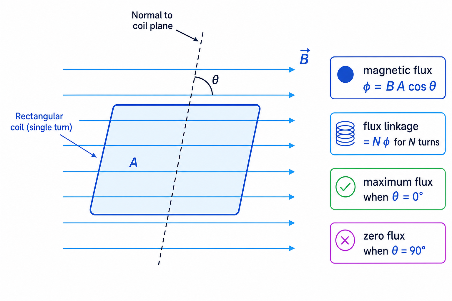
A normal is a line drawn at right angles to a surface. For a coil in a magnetic field, the angle in the flux equation is measured between the magnetic field and the normal to the coil, not the plane of the coil.
Definition
Magnetic flux and flux linkage
The magnetic flux through one turn of a coil in a uniform magnetic field is
Φ=BAcosθ\Phi = BA\cos\thetaΦ=BAcosθwhere BBB is magnetic flux density in tesla (T), AAA is area in square metres, and θ\thetaθ is the angle between the field and the normal. Magnetic flux is measured in webers (Wb). For a coil with NNN turns, the flux linkage is NΦN\PhiNΦ, measured in weber turns.
Flux is maximum when the normal is parallel to the field, so θ=0∘\theta = 0^\circθ=0∘. Flux is zero when the normal is perpendicular to the field, so $\theta = 90^\circ`.
Example
Calculating flux linkage
A 100-turn coil of area 2.0×10⁻³ m22.0 \times 10^{-3}\ \text{m}^22.0×10⁻³ m2 is in a uniform magnetic field of flux density 0.35 T0.35\ \text{T}0.35 T. The normal to the coil is at 60∘60^\circ60∘ to the field. Calculate the flux linkage.
- Use the angle between the field and the normal: θ=60∘\theta = 60^\circθ=60∘, so cos60∘=0.50\cos 60^\circ = 0.50cos60∘=0.50.
- Calculate the flux through one turn: Φ=BAcosθ=0.35×2.0×10−3×0.50=3.5×10⁻⁴ Wb\Phi = BA\cos\theta = 0.35 \times 2.0 \times 10^{-3} \times 0.50 = 3.5 \times 10^{-4}\ \text{Wb}Φ=BAcosθ=0.35×2.0×10−3×0.50=3.5×10⁻⁴ Wb.
- Multiply by the number of turns: NΦ=100×3.5×10−4=3.5×10⁻² Wb turnsN\Phi = 100 \times 3.5 \times 10^{-4} = 3.5 \times 10^{-2}\ \text{Wb turns}NΦ=100×3.5×10−4=3.5×10⁻² Wb turns.
Faraday’s law
Faraday’s law tells you the size of the induced emf.
Key Idea
Faraday’s law
The magnitude of the induced emf is equal to the rate of change of flux linkage.
For a coil:
ε=−Δ(NΦ)Δt\varepsilon = -\frac{\Delta(N\Phi)}{\Delta t}ε=−ΔtΔ(NΦ)If the number of turns is constant:
ε=−NΔΦΔt\varepsilon = -N\frac{\Delta\Phi}{\Delta t}ε=−NΔtΔΦThe minus sign is not for calculating the size. It represents Lenz’s law, which gives the direction of the induced emf.
Example
Calculating an induced emf
A 200-turn coil is placed with its normal parallel to a magnetic field. The coil area is 4.0×10⁻³ m24.0 \times 10^{-3}\ \text{m}^24.0×10⁻³ m2. The magnetic flux density increases from 0.20 T0.20\ \text{T}0.20 T to 0.65 T0.65\ \text{T}0.65 T in 0.080 s0.080\ \text{s}0.080 s. Calculate the magnitude of the average induced emf.
- The normal is parallel to the field, so cosθ=1\cos\theta = 1cosθ=1. The change in flux through one turn is ΔΦ=AΔB=4.0×10−3×(0.65−0.20)=1.8×10⁻³ Wb\Delta\Phi = A\Delta B = 4.0 \times 10^{-3} \times (0.65 - 0.20) = 1.8 \times 10^{-3}\ \text{Wb}ΔΦ=AΔB=4.0×10−3×(0.65−0.20)=1.8×10⁻³ Wb.
- Calculate the change in flux linkage: Δ(NΦ)=200×1.8×10−3=0.36 Wb turns\Delta(N\Phi) = 200 \times 1.8 \times 10^{-3} = 0.36\ \text{Wb turns}Δ(NΦ)=200×1.8×10−3=0.36 Wb turns.
- Divide by the time taken: ∣ε∣=0.360.080=4.5 V|\varepsilon| = \frac{0.36}{0.080} = 4.5\ \text{V}∣ε∣=0.0800.36=4.5 V.
Lenz’s law
Lenz’s law is the direction rule for induction.
Definition
Lenz’s law
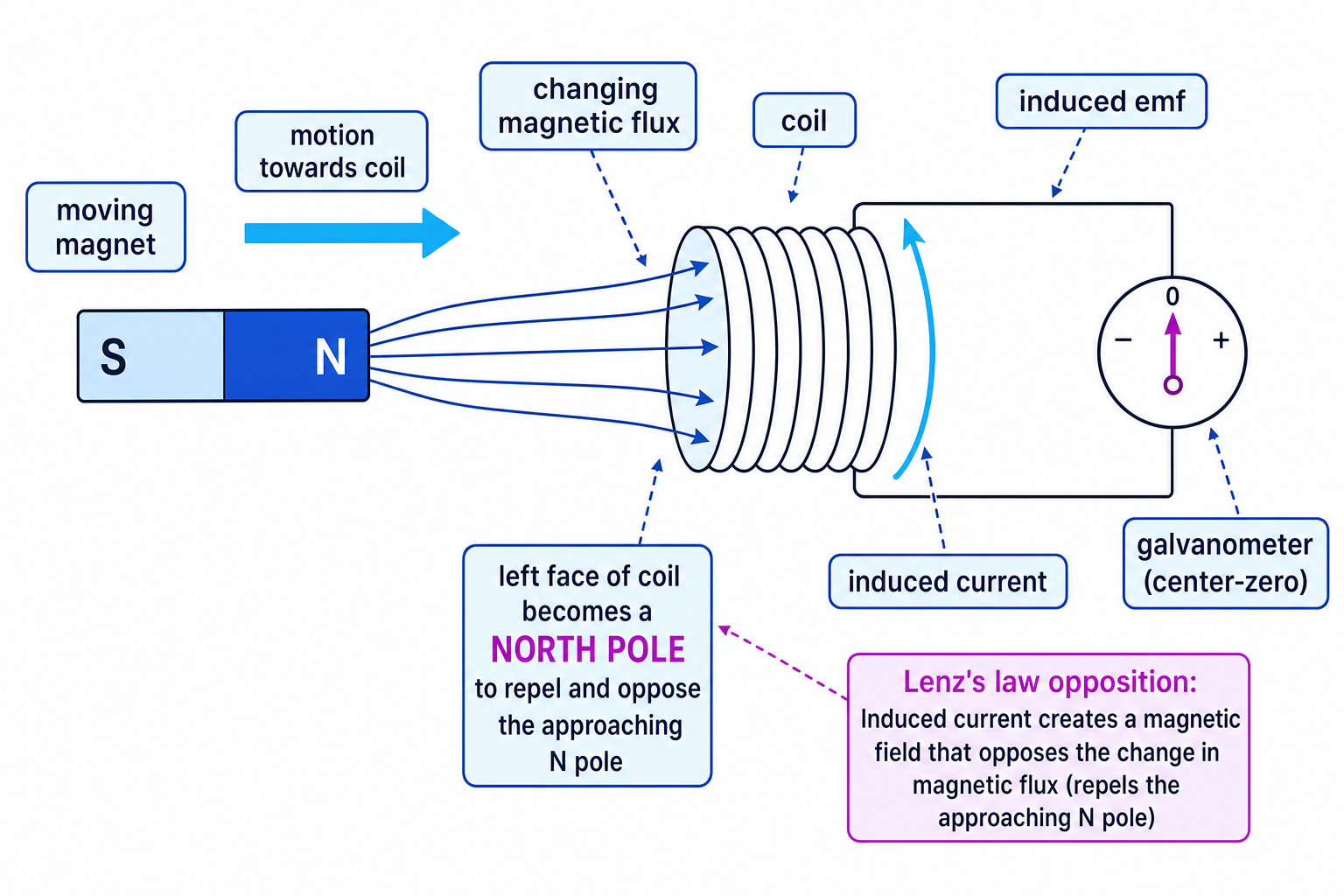
The direction of the induced emf, and any induced current, is such that it opposes the change that produced it.
For example, if a north pole moves towards a coil, the coil produces a magnetic field that opposes the increase in flux. The near face of the coil becomes a north pole, repelling the approaching north pole.
Tip
Lenz’s law is about change
The induced effect opposes the change in flux, not simply the magnetic field itself. If flux is increasing, the coil tries to reduce it. If flux is decreasing, the coil tries to maintain it.
To find the current direction in a coil, use the right-hand grip rule: curl your fingers in the current direction and your thumb points towards the coil’s north pole.
Example
Finding the induced pole of a coil
A north pole is pulled away from the left face of a coil. Decide what magnetic pole the left face of the coil becomes.
- The magnetic flux through the coil due to the nearby north pole is decreasing as the magnet moves away.
- To oppose this decrease, the coil must try to keep the magnet nearby by attracting the north pole.
- A face that attracts a north pole must be a south pole, so the left face of the coil becomes south.
Moving conductors: cutting field lines
A straight conductor can have an induced emf if it moves through a magnetic field. Free charges in the conductor experience a magnetic force, so charge separates along the conductor and a voltage is produced.
For a conductor of length ℓ\ellℓ moving at speed vvv at right angles to a uniform magnetic field:
ε=Bℓv\varepsilon = B\ell vε=BℓvCommon Mistake
Perpendicular formula
The equation ε=Bℓv\varepsilon = B\ell vε=Bℓv applies directly only when the conductor, its velocity, and the magnetic field are mutually perpendicular. Otherwise you need the perpendicular component.
Example
Calculating motional emf
A wire of length 0.30 m0.30\ \text{m}0.30 m moves at 2.5 m s−12.5\ \text{m s}^{-1}2.5 m s−1 at right angles to a magnetic field of flux density 0.80 T0.80\ \text{T}0.80 T. It is part of a circuit with total resistance 4.0 Ω4.0\ \Omega4.0 Ω. Calculate the induced current.
- The motion is perpendicular to the field, so use ε=Bℓv\varepsilon = B\ell vε=Bℓv.
- Calculate the emf: ε=0.80×0.30×2.5=0.60 V\varepsilon = 0.80 \times 0.30 \times 2.5 = 0.60\ \text{V}ε=0.80×0.30×2.5=0.60 V.
- Use I=VRI = \frac{V}{R}I=RV for the circuit current: I=0.604.0=0.15 AI = \frac{0.60}{4.0} = 0.15\ \text{A}I=4.00.60=0.15 A.
Generators and transformers
AC generators
In an AC generator, a coil rotates in a magnetic field. The flux linkage changes continuously, so an alternating emf is induced.
When the flux linkage is maximum, the rate of change of flux linkage is zero, so the induced emf is zero. When the flux linkage is changing fastest, the induced emf is maximum.
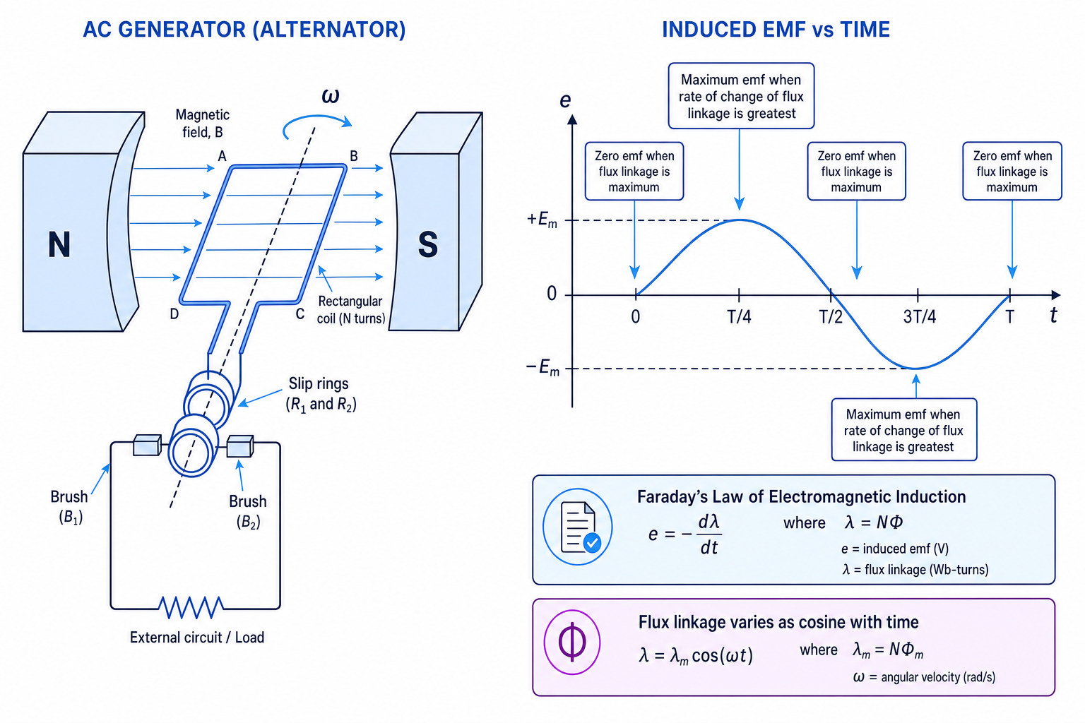
If a coil rotates steadily, the induced emf is sinusoidal. Increasing the magnetic flux density, coil area, number of turns, or rotation speed increases the maximum emf.
Transformers
A transformer uses induction between two coils. An alternating current in the primary coil produces a changing magnetic flux in the core, inducing an emf in the secondary coil.
For an ideal transformer:
VsVp=NsNp\frac{V_s}{V_p} = \frac{N_s}{N_p}VpVs=NpNsIf it is 100% efficient:
VpIp=VsIsV_p I_p = V_s I_sVpIp=VsIsA step-up transformer has more secondary turns than primary turns, so it increases voltage. A step-down transformer has fewer secondary turns, so it decreases voltage.
Common Mistake
Transformers need changing flux
A transformer needs an alternating current or changing current. A steady direct current gives no continuous induced emf in the secondary coil after the switching moment.
Example
Using the transformer equations
An ideal transformer has Np=600N_p = 600Np=600 turns and Ns=3000N_s = 3000Ns=3000 turns. The primary voltage is 230 V230\ \text{V}230 V and the secondary current is 0.20 A0.20\ \text{A}0.20 A. Calculate the secondary voltage and primary current.
- Use the turns ratio: Vs230=3000600=5\frac{V_s}{230} = \frac{3000}{600} = 5230Vs=6003000=5, so Vs=1150 VV_s = 1150\ \text{V}Vs=1150 V.
- Calculate the output power: Ps=VsIs=1150×0.20=230 WP_s = V_s I_s = 1150 \times 0.20 = 230\ \text{W}Ps=VsIs=1150×0.20=230 W.
- For an ideal transformer, input power equals output power, so Ip=230230=1.0 AI_p = \frac{230}{230} = 1.0\ \text{A}Ip=230230=1.0 A.
Practical note
You can observe induction using a coil connected to a centre-zero galvanometer or data logger. Moving a magnet faster gives a larger deflection because the rate of change of flux linkage is greater. Reversing the magnet’s motion reverses the deflection, showing that the induced emf has changed direction.
Exam technique
In the exam
- Draw the coil normal, then decide whether flux linkage is increasing or decreasing.
- Use Faraday’s law for the magnitude of the emf, and Lenz’s law for the direction.
- Convert areas to square metres and times to seconds before substituting.
- For transformers, check that the question assumes an ideal transformer before using equal input and output power.
Self review
Check yourself
- Why is the induced emf zero when the flux linkage is maximum in a rotating coil?
- A south pole moves towards a coil. What pole does the near face of the coil become?
- What happens to the secondary current in an ideal step-up transformer if the voltage increases?
You've reached the end
Test yourself on this topic, or move on to the next guide.
How was this guide?