Revision notes for Edexcel A Level Physics Capacitors and RC circuits. Open the guide for explanations and worked examples. Written against the Edexcel A Level Physics (9PH0) specification, so the content matches what's examinable rather than general Physics background.
Capacitors and RC circuits
What you'll learn
- What a capacitor is and what capacitance measures.
- How to calculate charge, potential difference, and energy stored.
- How capacitors behave when charging and discharging through a resistor.
- How to use the time constant and exponential graphs in RC circuits.
Prerequisite ideas: charge, current, and potential difference
Before capacitors, you need three circuit quantities to feel secure.
Electric charge is a property of particles, measured in coulombs, C. In circuits, moving charge is what makes current.
Current is the rate of flow of charge:
I=ΔQΔtI = \frac{\Delta Q}{\Delta t}I=ΔtΔQPotential difference is the energy transferred per unit charge between two points:
V=WQV = \frac{W}{Q}V=QWA resistor is a component that opposes current. For an ohmic resistor, V=IRV = IRV=IR.
What is a capacitor?
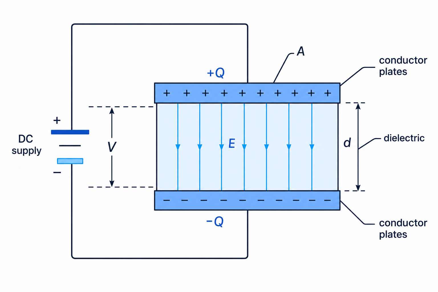
A capacitor is a component designed to store charge and energy. The simplest model is two conducting plates separated by an insulator. The insulating material between the plates is called a dielectric.
When a capacitor is connected to a direct current supply, electrons are moved from one plate to the other. One plate becomes negatively charged and the other becomes positively charged. The plates have equal and opposite charges, usually written as +Q+Q+Q and −Q-Q−Q.
The separated charges create an electric field, which is a region where a charge would experience a force. For large parallel plates, the field between the plates is approximately uniform, and its strength is related to the plate potential difference by E=VdE = \frac{V}{d}E=dV, where ddd is the plate separation.
Key Idea
What a capacitor stores
A capacitor does not store current. It stores separated charge and therefore stores energy in the electric field between its plates.
Capacitance
Capacitance tells you how much charge a capacitor stores for each volt across it.
Definition
Capacitance
Capacitance, CCC, is defined by C=QVC = \frac{Q}{V}C=VQ, where QQQ is the magnitude of charge stored on one plate and VVV is the potential difference across the capacitor.
Rearranging gives the most-used form:
Q=CVQ = CVQ=CVThe unit of capacitance is the farad, F. One farad means one coulomb stored per volt. In practical A-Level circuits, capacitors are often measured in microfarads, μF\mu\text{F}μF, or millifarads, mF.
For a fixed capacitor, charge is directly proportional to potential difference, so a graph of QQQ against VVV is a straight line through the origin. The gradient is the capacitance.
Example
Calculating charge stored
A 470 μF470\ \mu\text{F}470 μF capacitor is connected across a 12.0 V supply. Find the charge stored on each plate.
-
Convert the capacitance into farads:
470 μF=470×10−6 F470\ \mu\text{F} = 470 \times 10^{-6}\ \text{F}470 μF=470×10−6 F. -
Use Q=CVQ = CVQ=CV:
Q=(470×10−6)(12.0)Q = \left(470 \times 10^{-6}\right)\left(12.0\right)Q=(470×10−6)(12.0). -
Calculate and quote a sensible number of significant figures:
Q=5.64×10⁻³ CQ = 5.64 \times 10^{-3}\ \text{C}Q=5.64×10⁻³ C, so the charge stored is 5.64 mC5.64\ \text{mC}5.64 mC.
Common Mistake
Final p.d. is not instant
When a capacitor is charging through a resistor, the capacitor potential difference is not immediately equal to the supply potential difference. It only reaches the supply value after a long time in the ideal model.
Energy stored in a capacitor
As a capacitor charges, it becomes harder to push more charge onto the plates because the potential difference is increasing. The energy stored is the work done to separate the charge.
On a graph of VVV against QQQ, the energy stored is the area under the line. Since the graph is triangular:
Estored=12QVE_{\text{stored}} = \frac{1}{2}QVEstored=21QVUsing Q=CVQ = CVQ=CV, you also need these equivalent forms:
Estored=12CV2=Q22CE_{\text{stored}} = \frac{1}{2}CV^2 = \frac{Q^2}{2C}Estored=21CV2=2CQ2Example
Finding energy stored
A 2200 μF2200\ \mu\text{F}2200 μF capacitor is charged to 9.0 V. Find the energy stored.
-
Convert the capacitance:
2200 μF=2.20×10⁻³ F2200\ \mu\text{F} = 2.20 \times 10^{-3}\ \text{F}2200 μF=2.20×10⁻³ F. -
Choose the energy equation using the given quantities:
Estored=12CV2E_{\text{stored}} = \frac{1}{2}CV^2Estored=21CV2. -
Substitute carefully:
Estored=12(2.20×10⁻³)(9.0)2=8.91×10⁻² JE_{\text{stored}} = \frac{1}{2}\left(2.20 \times 10^{-3}\right)\left(9.0\right)^2 = 8.91 \times 10^{-2}\ \text{J}Estored=21(2.20×10⁻³)(9.0)2=8.91×10⁻² J.
Tip
Voltage matters a lot
Because Estored=12CV2E_{\text{stored}} = \frac{1}{2}CV^2Estored=21CV2, doubling the voltage stores four times as much energy, provided the capacitance is unchanged.
Capacitors in series and parallel
Sometimes capacitors are combined into networks. The equivalent capacitance is the single capacitance that would have the same overall effect.
For capacitors in parallel, each capacitor has the same potential difference. Charges add:
Ctotal=C1+C2+C3+⋯C_{\text{total}} = C_1 + C_2 + C_3 + \cdotsCtotal=C1+C2+C3+⋯For capacitors in series, each capacitor stores the same magnitude of charge. Potential differences add:
1Ctotal=1C1+1C2+1C3+⋯\frac{1}{C_{\text{total}}} = \frac{1}{C_1} + \frac{1}{C_2} + \frac{1}{C_3} + \cdotsCtotal1=C11+C21+C31+⋯Example
Combining capacitors in series
A 2.0 μF2.0\ \mu\text{F}2.0 μF capacitor and a 3.0 μF3.0\ \mu\text{F}3.0 μF capacitor are connected in series across 12 V. Find the total capacitance and the p.d. across each capacitor.
-
Use the series rule:
1Ctotal=12.0+13.0=56\frac{1}{C_{\text{total}}} = \frac{1}{2.0} + \frac{1}{3.0} = \frac{5}{6}Ctotal1=2.01+3.01=65 in units of μF−1\mu\text{F}^{-1}μF−1, so Ctotal=1.2 μFC_{\text{total}} = 1.2\ \mu\text{F}Ctotal=1.2 μF. -
In series, the charge is the same on both capacitors:
Q=CtotalV=(1.2 μF)(12 V)=14.4 μCQ = C_{\text{total}}V = \left(1.2\ \mu\text{F}\right)\left(12\ \text{V}\right) = 14.4\ \mu\text{C}Q=CtotalV=(1.2 μF)(12 V)=14.4 μC. -
Find each p.d. using V=QCV = \frac{Q}{C}V=CQ:
across 2.0 μF2.0\ \mu\text{F}2.0 μF, V=7.2 VV = 7.2\ \text{V}V=7.2 V; across 3.0 μF3.0\ \mu\text{F}3.0 μF, V=4.8 VV = 4.8\ \text{V}V=4.8 V. These add to 12 V.
RC circuits
An RC circuit contains a resistor, RRR, and a capacitor, CCC. These circuits are important because charge, potential difference, and current change exponentially with time.
An exponential change means the quantity changes by the same fraction in equal time intervals. In capacitor discharge, for example, the voltage falls quickly at first, then more slowly.
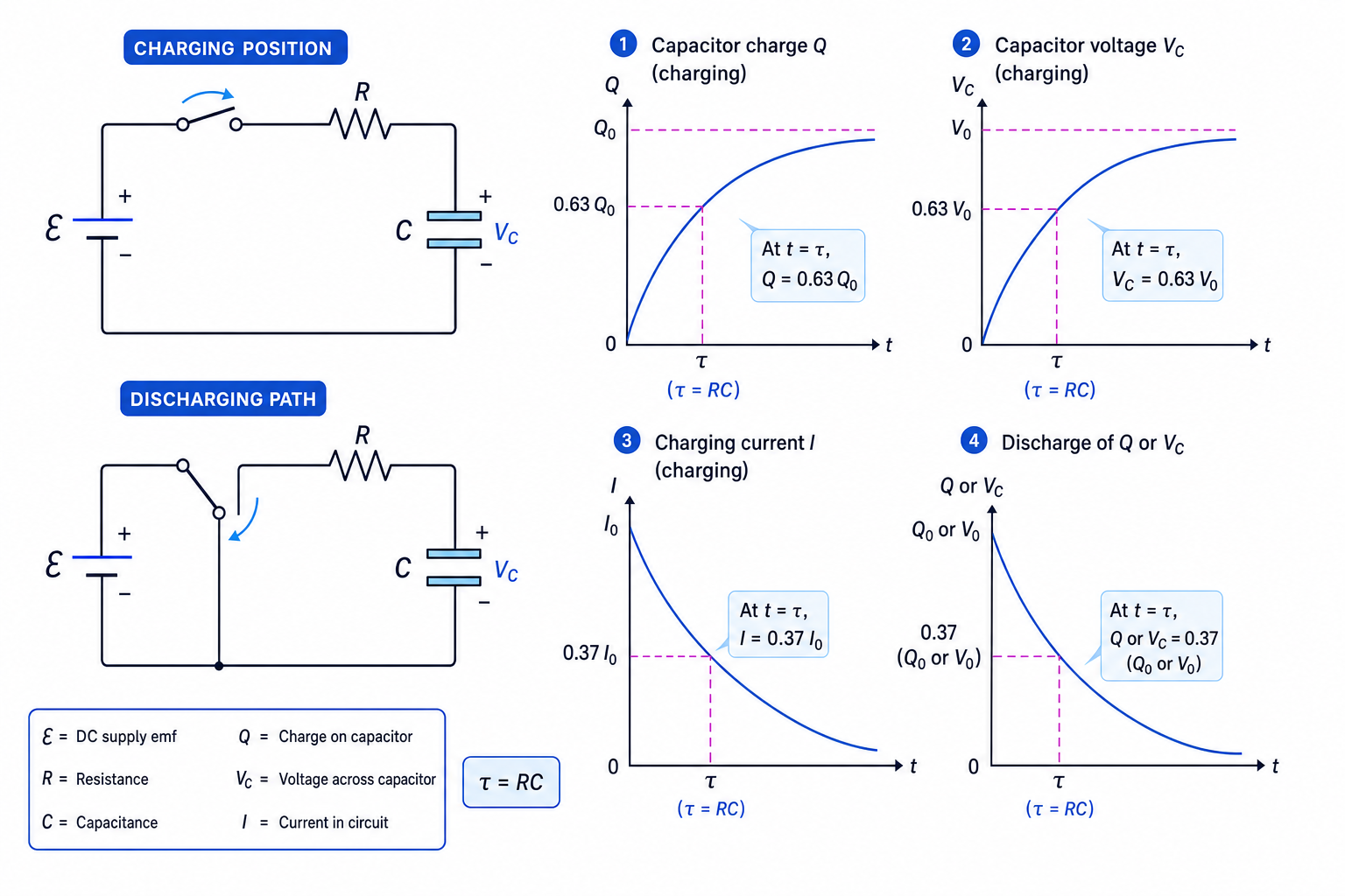
The diagram below summarises the key charging and discharging circuits and graphs.
Charging through a resistor
At the start of charging, the capacitor is uncharged, so VC=0V_C = 0VC=0. The initial current is maximum:
I0=ERI_0 = \frac{\mathcal{E}}{R}I0=REAs charge builds up, the capacitor potential difference increases. This reduces the p.d. across the resistor, so the current decreases.
For charging from zero:
Q=Q0(1−e−t/RC)VC=V0(1−e−t/RC)I=I0e−t/RC\begin{aligned} Q &= Q_0\left(1 - e^{-t/RC}\right) \\ V_C &= V_0\left(1 - e^{-t/RC}\right) \\ I &= I_0e^{-t/RC} \end{aligned}QVCI=Q0(1−e−t/RC)=V0(1−e−t/RC)=I0e−t/RCHere V0V_0V0 is the final capacitor p.d., equal to the supply emf E\mathcal{E}E for an ideal circuit, and Q0=CV0Q_0 = CV_0Q0=CV0.
Discharging through a resistor
During discharge, the capacitor is no longer connected to the supply. The stored charge drives a current through the resistor. The capacitor p.d., charge, and current magnitude all decrease exponentially:
Q=Q0e−t/RCVC=V0e−t/RCI=I0e−t/RC\begin{aligned} Q &= Q_0e^{-t/RC} \\ V_C &= V_0e^{-t/RC} \\ I &= I_0e^{-t/RC} \end{aligned}QVCI=Q0e−t/RC=V0e−t/RC=I0e−t/RCCommon Mistake
Current direction during discharge
If current was defined as positive during charging, then the discharge current is usually in the opposite direction. Many equations give the magnitude of current, so check the sign convention in the question.
The time constant
Definition
Time constant
The time constant of an RC circuit is τ=RC\tau = RCτ=RC. It is measured in seconds and tells you how quickly the capacitor charges or discharges.
After one time constant during charging, the capacitor has reached about 63% of its final charge or voltage. During discharge, it has fallen to about 37% of its initial charge or voltage.
After about five time constants, charging or discharging is usually treated as almost complete.
Example
Using RC discharge data
A capacitor discharges through a 220 kΩ220\ \text{k}\Omega220 kΩ resistor. A graph of lnVC\ln V_ClnVC against time has gradient −0.091 s−1-0.091\ \text{s}^{-1}−0.091 s−1. The initial capacitor voltage is 6.0 V. Find the capacitance and the voltage after 20 s.
-
For discharge, VC=V0e−t/RCV_C = V_0e^{-t/RC}VC=V0e−t/RC, so lnVC=lnV0−tRC\ln V_C = \ln V_0 - \frac{t}{RC}lnVC=lnV0−RCt. Therefore the graph gradient is −1RC-\frac{1}{RC}−RC1.
-
Rearrange for capacitance using the magnitude of the gradient:
C=1R∣m∣=1(220×103)(0.091)=4.99×10⁻⁵ FC = \frac{1}{R\left|m\right|} = \frac{1}{\left(220 \times 10^3\right)\left(0.091\right)} = 4.99 \times 10^{-5}\ \text{F}C=R∣m∣1=(220×103)(0.091)1=4.99×10⁻⁵ F. -
Convert to a sensible unit and find the time constant:
C≈50 μFC \approx 50\ \mu\text{F}C≈50 μF and τ=RC=10.091≈11 s\tau = RC = \frac{1}{0.091} \approx 11\ \text{s}τ=RC=0.0911≈11 s. -
Use the discharge equation:
VC=6.0e−20/11=0.98 VV_C = 6.0e^{-20/11} = 0.98\ \text{V}VC=6.0e−20/11=0.98 V to two significant figures.
Practical graph work
A common practical method is to charge a capacitor, then let it discharge through a known resistor while recording the capacitor voltage using a voltmeter or data logger.
A direct graph of VCV_CVC against time is curved, so it can be hard to get an accurate gradient. A graph of lnVC\ln V_ClnVC against time should be a straight line for an ideal discharge. Its gradient is −1RC-\frac{1}{RC}−RC1, so you can calculate CCC if RRR is known.
Tip
Checking an RC graph
On a discharge graph, the curve should be steepest at the start and should never cross the time axis. If your plotted voltage becomes negative in an ideal discharge model, something has gone wrong with the model, measurement, or sign convention.
Exam technique
In the exam
- Identify whether the capacitor is charging or discharging before choosing the equation.
- Convert prefixes carefully, especially μF\mu\text{F}μF, mF, and kΩ\text{k}\OmegakΩ.
- For graph questions, link the gradient to −1RC-\frac{1}{RC}−RC1 and use the magnitude when calculating CCC.
- Remember that energy depends on V2V^2V2, so voltage changes have a large effect.
Self review
Check yourself
- Why does the current decrease as a capacitor charges through a resistor?
- What fraction of its initial voltage remains after one time constant during discharge?
- How would you find capacitance from a graph of lnVC\ln V_ClnVC against time?
You've reached the end
Test yourself on this topic, or move on to the next guide.
How was this guide?