13.2.1 Transformers and induction
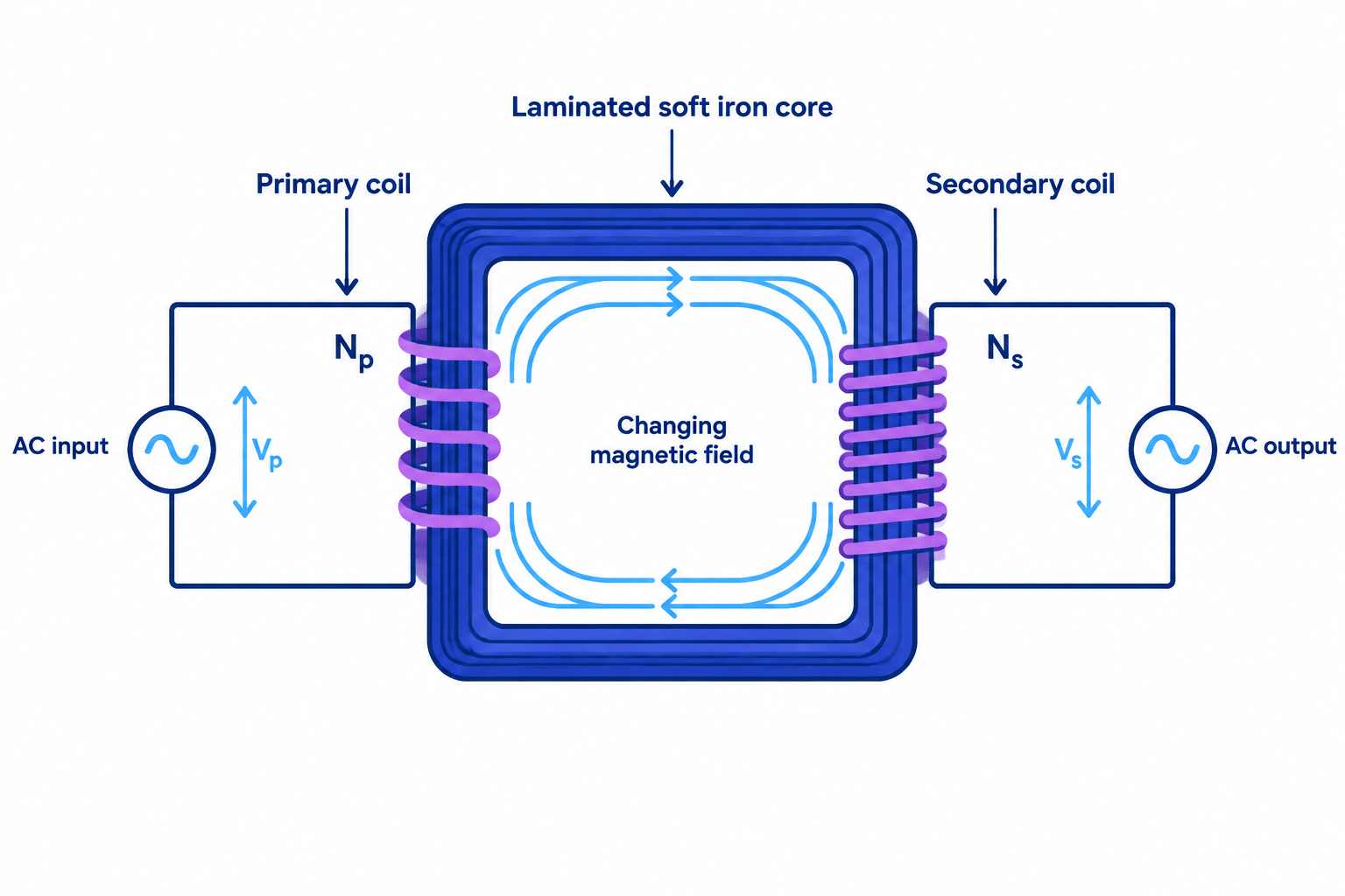
Parts of a transformer
Transformer
A transformer is a device that uses electromagnetic induction between two coils on a shared iron core to change the size of an alternating potential difference.
- A transformer is built from a primary coil, a secondary coil and a core of soft iron that both coils are wound onto.
- The primary coil is connected to the input supply, and the secondary coil is connected to the output circuit.
- The two coils are insulated from each other and from the core, so there is no complete circuit joining the primary to the secondary and no charge passes between them.
- Soft iron is used for the core because it is easily magnetised and demagnetised, so the magnetic field in the core follows the changing current in the primary almost instantly.
- The core is normally built from thin sheets of iron, called laminations, with insulation between them.
- On a circuit diagram the two coils are drawn on either side of two parallel lines that represent the core, with no wire crossing between them.
How a transformer works
Electromagnetic induction
Electromagnetic induction is the production of a potential difference across the ends of a conductor when the magnetic field through that conductor changes.
- An alternating current in the primary coil produces a magnetic field in and around that coil.
- Because the current is constantly changing in size and reversing in direction, the magnetic field it produces is also constantly changing in size and reversing in direction.
- The soft iron core carries this changing magnetic field round to the secondary coil, so almost all of the field produced by the primary passes through the secondary.
- The changing magnetic field through the secondary coil induces an alternating potential difference across its ends.
- A current flows in the secondary only when its circuit is complete, so an unloaded transformer still has a potential difference across its secondary.
- The output has the same frequency as the input, because the field in the core completes one full change for every cycle of the primary current.
- Energy is transferred from the primary circuit to the secondary circuit by the changing magnetic field alone, which is why the two circuits can be kept electrically separate.
Why transformers need alternating current
Alternating current
Alternating current is a current that repeatedly reverses its direction of flow.
- A direct current in the primary coil produces a magnetic field that is steady in both size and direction.
- A steady field through the secondary coil is not changing, so nothing is induced and the output stays at zero for as long as the direct current flows.
- A brief potential difference does appear across the secondary at the instant a direct supply is switched on or off, because the field in the core grows or collapses at that moment.
- A transformer therefore cannot raise or lower the potential difference of a battery, and needs a supply that is changing all the time.
- This is one of the reasons that electricity is generated and transmitted as alternating current rather than direct current.
Energy losses in a real transformer
Dissipation
Dissipation is the transfer of energy to the thermal store of the surroundings, where it becomes spread out and can no longer be used usefully.
- The coils are made of wire with resistance, so the currents in them heat the wire and energy is dissipated to the surroundings.
- Thick copper wire is used to keep this resistance low, which is why the coils of a large transformer are heavy.
- The changing magnetic field also induces unwanted currents in the iron core itself, and these currents heat the core.
- Building the core from thin insulated laminations rather than one solid block restricts those unwanted currents and reduces the heating.
- Repeatedly magnetising and demagnetising the core transfers energy to it as well, which is another reason soft iron is chosen rather than steel.
- Large transformers are cooled by oil and fins so that the energy dissipated does not raise their temperature to a damaging level.
- A well-built transformer wastes only a small fraction of the power passing through it, which is why transformer questions normally treat one as being 100%100\%100% efficient.
Demonstrating that a transformer needs alternating current
- Aim: to show that a transformer produces an output only when the current in its primary coil is changing, and to show that the core carries the field between the coils.
- Apparatus: demountable transformer kit with a laminated C-core and yoke, two coils of known turns such as 600600600 turns and 300300300 turns, low-voltage alternating supply, low-voltage direct supply with a tapping key or switch, two multimeters set to measure alternating and direct potential difference, low-voltage lamp with holder, oscilloscope or data logger, and connecting leads.
- Variables: the type of supply connected to the primary coil is the independent variable, the potential difference across the secondary coil is the dependent variable, and the two coils, their turns, the core and the supply setting are controlled.
- Method, setting up:
- Slide the two coils onto the C-core, clamp the yoke firmly across the open ends so the core forms a closed loop, and check that no wire joins the two coils.
- Connect the primary coil to the low-voltage alternating supply set to a low value, and connect the secondary coil to a multimeter.
- Record the number of turns on each coil and the setting of the supply before taking any readings.
- Method, using an alternating supply:
- Switch on the alternating supply and record the potential differences across the primary and the secondary coils.
- Replace the multimeter with the lamp and observe that the lamp lights even though no wire connects it to the supply.
- Connect the oscilloscope across the secondary and sketch the trace, noting that the output alternates at the same frequency as the input.
- Method, using a direct supply:
- Switch off, replace the alternating supply with the direct supply at the same setting, and connect the multimeter set to measure direct potential difference across the secondary.
- Close the tapping key and hold it closed, then record the steady reading on the secondary, which stays at zero.
- Watch the meter or the oscilloscope closely while the key is closed and again while it is opened, and record the brief kick of the reading at each switching moment.
- Tap the key repeatedly and note that a reading appears only at the instants of switching, not while the current flows steadily.
- Method, testing the role of the core:
- Return to the alternating supply, then loosen and remove the yoke so that the core is no longer a closed loop, and record the new secondary reading.
- Lift one coil off the core entirely and hold it near the other, then record how small the reading becomes.
- Measurements and processing: tabulate the supply type, the primary potential difference and the secondary potential difference for each arrangement, and note whether the output is steady, alternating or momentary.
- Expected pattern: the alternating supply gives a steady alternating output, the direct supply gives no output except at the moments of switching, removing the yoke reduces the output sharply, and separating the coils reduces it almost to nothing.
- Sources of uncertainty: a loose yoke leaves an air gap that varies between runs, the coils may not be pushed fully onto the core, the meter may be too slow to show the switching kick, and the coils warm up and change resistance during a long run.
- Improvements: clamp the yoke to the same tightness each time, use an oscilloscope or data logger rather than a meter so the switching kick is visible, and keep each run short so the coils stay cool.
- Safety: use only low-voltage supplies, switch off before rearranging the core or the coils, do not touch the coils after a long run because they become hot, and keep the tapping key closed only briefly so the primary is not overheated.
Describing the transformer chain
- State the input: an alternating potential difference is applied across the primary coil, driving an alternating current in it.
- State the field: the alternating current produces a magnetic field that is constantly changing in size and direction.
- State the link: the soft iron core carries the changing magnetic field to the secondary coil.
- State the output: the changing field through the secondary coil induces an alternating potential difference across it.
- Every link in that chain carries a separate mark, so leaving out the core or the word changing costs marks even when the rest of the answer is right.
Why a phone charger hums
- A charger plugged into a 230 V230\ \text{V}230 V mains socket contains a transformer whose primary coil carries an alternating current at 50 Hz50\ \text{Hz}50 Hz.
- The magnetic field in the core therefore builds up and collapses 100100100 times each second, twice in every cycle of the current.
- Each build-up and collapse pulls the laminations of the core very slightly together and lets them spring apart again.
- The laminations vibrate at 100 Hz100\ \text{Hz}100 Hz and push on the surrounding air, which is heard as a low hum.
- The charger also becomes warm because the coils have resistance and unwanted currents are induced in the core.
- A charger left plugged in with nothing connected still hums, because the primary current and the changing field are present even when the secondary circuit is open.
Writing a transformer explanation
- Use the word changing every time you mention the magnetic field, because a field that is merely present induces nothing.
- Name the soft iron core as the part that carries the field from one coil to the other, rather than saying the field simply reaches the secondary.
- State that the coils are not electrically connected when a question asks how energy crosses the transformer.
- For a question about a direct supply, say that the field is steady, so nothing is induced, and add that a brief output appears at switch-on and switch-off.
- When asked why a transformer becomes warm, name a specific loss such as resistance heating in the coils rather than writing about energy being wasted.
- Do not write that current passes from the primary coil to the secondary coil, because the two circuits are separate and only the magnetic field links them.
- Do not say that a transformer works on a battery supply, since a steady current produces a steady field and induces nothing.
- Do not describe the core as a conductor of electricity between the coils, because its job is to carry the magnetic field.
- Do not claim that a transformer changes the frequency of the supply, since the output frequency always equals the input frequency.
- Do not use hard steel or a plastic core in a description, because soft iron is needed so the field can change as fast as the current does.
- Name the three main parts of a transformer and state what each one does.
- Describe the chain of events from an alternating current in the primary coil to an induced potential difference across the secondary coil.
- Explain why a transformer connected to a battery gives no steady output.
- Explain why the core of a transformer is made of soft iron rather than steel.
- Give two reasons why a real transformer becomes warm in use.
13.2.2 The transformer turns-ratio equation
The turns-ratio equation
Turns ratio
The turns ratio of a transformer is the number of turns on its primary coil divided by the number of turns on its secondary coil.
Step-up transformer
A step-up transformer is a transformer with more turns on its secondary coil than on its primary coil, so the output potential difference is larger than the input potential difference.
Step-down transformer
A step-down transformer is a transformer with fewer turns on its secondary coil than on its primary coil, so the output potential difference is smaller than the input potential difference.
- The potential differences and the numbers of turns of a transformer are linked by VpVs=NpNs\dfrac{V_{\mathrm{p}}}{V_{\mathrm{s}}}=\dfrac{N_{\mathrm{p}}}{N_{\mathrm{s}}}VsVp=NsNp.
- In that equation VpV_{\mathrm{p}}Vp is the primary potential difference in volts, VsV_{\mathrm{s}}Vs is the secondary potential difference in volts, NpN_{\mathrm{p}}Np is the number of turns on the primary coil and NsN_{\mathrm{s}}Ns is the number of turns on the secondary coil.
- The ratio of the potential differences matches the ratio of the turns because the same changing magnetic field passes through every turn of both coils, so each turn has the same potential difference induced across it.
- A coil with more turns therefore has more of those equal contributions added in series, which is why more turns means a larger potential difference.
- A step-up transformer has Ns>NpN_{\mathrm{s}}>N_{\mathrm{p}}Ns>Np, so Vs>VpV_{\mathrm{s}}>V_{\mathrm{p}}Vs>Vp and the potential difference is raised.
- A step-down transformer has Ns<NpN_{\mathrm{s}}<N_{\mathrm{p}}Ns<Np, so Vs<VpV_{\mathrm{s}}<V_{\mathrm{p}}Vs<Vp and the potential difference is lowered.
- Equal numbers of turns give Vs=VpV_{\mathrm{s}}=V_{\mathrm{p}}Vs=Vp, which is useful when two circuits must be kept electrically separate without changing the potential difference.
- The turns ratio NpNs\dfrac{N_{\mathrm{p}}}{N_{\mathrm{s}}}NsNp is a pure number with no unit, so a transformer described as 10:110:110:1 steps the potential difference down by a factor of ten.
Using and rearranging the equation
- The rearranged forms are Vs=VpNsNpV_{\mathrm{s}}=\dfrac{V_{\mathrm{p}}N_{\mathrm{s}}}{N_{\mathrm{p}}}Vs=NpVpNs, Vp=VsNpNsV_{\mathrm{p}}=\dfrac{V_{\mathrm{s}}N_{\mathrm{p}}}{N_{\mathrm{s}}}Vp=NsVsNp, Ns=NpVsVpN_{\mathrm{s}}=\dfrac{N_{\mathrm{p}}V_{\mathrm{s}}}{V_{\mathrm{p}}}Ns=VpNpVs and Np=NsVpVsN_{\mathrm{p}}=\dfrac{N_{\mathrm{s}}V_{\mathrm{p}}}{V_{\mathrm{s}}}Np=VsNsVp.
- List the four quantities and label each one as primary or secondary before substituting, because swapping a pair turns a step-up answer into a step-down answer.
- Convert every potential difference into the same unit first, so 132 kV132\ \text{kV}132 kV becomes 132 000 V132\,000\ \text{V}132000 V and 25 mV25\ \text{mV}25 mV becomes 0.025 V0.025\ \text{V}0.025 V.
- Numbers of turns are counted, so they never carry a unit and must never be rounded to a fraction of a turn.
- A useful shortcut is to work out the ratio first: if the secondary has 120\dfrac{1}{20}201 of the turns, the secondary potential difference is 120\dfrac{1}{20}201 of the primary potential difference.
- Check the finished answer against the turns: the coil with more turns must always be the one with the larger potential difference.
Finding an output potential difference
- A transformer has 115011501150 turns on its primary coil and 505050 turns on its secondary coil, and its primary is connected to a 230 V230\ \text{V}230 V alternating supply.
- Rearranging the turns-ratio equation gives Vs=VpNsNpV_{\mathrm{s}}=\dfrac{V_{\mathrm{p}}N_{\mathrm{s}}}{N_{\mathrm{p}}}Vs=NpVpNs.
- Substituting gives Vs=230×501150V_{\mathrm{s}}=\dfrac{230\times50}{1150}Vs=1150230×50.
- The secondary potential difference is Vs=10 VV_{\mathrm{s}}=10\ \text{V}Vs=10 V.
- The secondary has fewer turns than the primary, so this is a step-down transformer and the smaller output is the expected result.
Finding a number of turns
- A power station transformer raises an alternating potential difference from 25 kV25\ \text{kV}25 kV to 400 kV400\ \text{kV}400 kV, and its primary coil has 500500500 turns.
- Both potential differences are converted to volts, giving Vp=25 000 VV_{\mathrm{p}}=25\,000\ \text{V}Vp=25000 V and Vs=400 000 VV_{\mathrm{s}}=400\,000\ \text{V}Vs=400000 V.
- Rearranging the turns-ratio equation gives Ns=NpVsVpN_{\mathrm{s}}=\dfrac{N_{\mathrm{p}}V_{\mathrm{s}}}{V_{\mathrm{p}}}Ns=VpNpVs.
- Substituting gives Ns=500×400 00025 000N_{\mathrm{s}}=\dfrac{500\times400\,000}{25\,000}Ns=25000500×400000.
- The secondary coil needs Ns=8000N_{\mathrm{s}}=8000Ns=8000 turns.
- The potential difference has been raised by a factor of 161616, and the number of turns has risen by the same factor of 161616, which confirms the arithmetic.
Measuring the turns ratio of a demountable transformer
- Aim: to test whether the ratio of the potential differences across two coils equals the ratio of their numbers of turns.
- Apparatus: demountable transformer kit with a laminated C-core and clamping yoke, a set of coils of known turns such as 300300300, 600600600 and 120012001200 turns, low-voltage alternating supply, two multimeters or a data logger with two voltage sensors, and connecting leads.
- Variables: the number of turns on the secondary coil is the independent variable, the secondary potential difference is the dependent variable, and the primary coil, the primary potential difference, the core, the yoke tightness and the supply frequency are controlled.
- Method, setting up:
- Slide the 600600600 turn coil onto one arm of the C-core to act as the primary, and a coil of known turns onto the other arm to act as the secondary.
- Clamp the yoke firmly across the open ends of the core so the magnetic circuit is closed, and use the same tightness for every run.
- Connect the primary to the low-voltage alternating supply set to about 4 V4\ \text{V}4 V, and connect a meter across each coil so both potential differences are read at the same moment.
- Record the number of turns marked on each coil before switching on.
- Method, taking the readings:
- Switch on, read the primary and secondary potential differences together, then switch off promptly so the coils do not warm up.
- Repeat the reading three times, switching off between runs, and calculate a mean for each potential difference.
- Swap the secondary for a coil with a different number of turns without moving the primary or altering the supply, and repeat the readings.
- Collect results for at least four different secondary coils, including one with fewer turns than the primary and one with more.
- Reverse the roles of the two coils for one pair, so the step-down arrangement becomes a step-up arrangement, and check that the ratio inverts.
- Measurements and processing: tabulate NpN_{\mathrm{p}}Np, NsN_{\mathrm{s}}Ns, VpV_{\mathrm{p}}Vp and VsV_{\mathrm{s}}Vs with the mean values, then calculate NpNs\dfrac{N_{\mathrm{p}}}{N_{\mathrm{s}}}NsNp and VpVs\dfrac{V_{\mathrm{p}}}{V_{\mathrm{s}}}VsVp for each pair and compare the two columns.
- Graph: plot VsV_{\mathrm{s}}Vs against NsN_{\mathrm{s}}Ns for a fixed primary, which should give a straight line through the origin.
- Expected pattern: the two ratios agree closely, and the measured secondary potential difference is usually a little lower than the predicted value because the transformer is not perfectly efficient.
- Sources of uncertainty: an air gap left by a loose yoke reduces the field reaching the secondary, the coils warm up and their resistance rises during a run, meters have a limited resolution on low readings, and the supply potential difference may drift.
- Improvements: clamp the yoke to a fixed tightness every time, monitor the primary potential difference throughout so any drift is spotted, keep each run short, and use a data logger so both readings are captured at the same instant.
- Safety: use only the low-voltage alternating supply, never connect a demountable transformer to the mains, switch off before rearranging the coils or the core, and allow warm coils to cool before handling them.
Identifying the type of transformer
- Count the turns on each coil in a diagram: the coil drawn with more loops is the one with the larger potential difference.
- Compare the two potential differences instead when the turns are not given, since a larger output means a step-up transformer.
- Use the ratio as a factor: a transformer with NpNs=116\dfrac{N_{\mathrm{p}}}{N_{\mathrm{s}}}=\dfrac{1}{16}NsNp=161 multiplies the potential difference by 161616.
- Read the labels carefully, because a transformer is only a step-up transformer with respect to the coil chosen as the primary.
Setting out a turns-ratio calculation
- Write VpVs=NpNs\dfrac{V_{\mathrm{p}}}{V_{\mathrm{s}}}=\dfrac{N_{\mathrm{p}}}{N_{\mathrm{s}}}VsVp=NsNp before substituting, so the method earns credit even if the arithmetic slips.
- List the given values with their subscripts, then rearrange for the unknown as a separate line.
- Convert kilovolts and millivolts into volts in a visible step rather than doing it in your head.
- Give the answer with a unit, in volts for a potential difference and with no unit for a number of turns.
- Finish by stating whether the transformer is step-up or step-down, since many questions award a mark for that comparison.
- Do not swap the primary and secondary values, because the equation is symmetrical and the arithmetic gives no warning.
- Do not leave a potential difference in kilovolts alongside one in volts when substituting.
- Do not give a number of turns as a decimal, since turns of wire are counted in whole numbers.
- Do not assume that a step-up transformer increases the power available, because raising the potential difference lowers the current.
- Do not use the turns-ratio equation on a direct supply, since no potential difference is induced when the field is steady.
- State the turns-ratio equation and identify each of its four quantities.
- Explain why a coil with more turns has a larger potential difference across it.
- Calculate the secondary potential difference of a transformer with 200020002000 primary turns, 400400400 secondary turns and a 230 V230\ \text{V}230 V primary supply.
- Calculate the number of primary turns needed to step 12 kV12\ \text{kV}12 kV up to 132 kV132\ \text{kV}132 kV using 150150150 secondary turns.
- Describe how to test the turns-ratio equation using a demountable transformer.
13.2.3 The National Grid
What the National Grid does
National Grid
The National Grid is the nationwide network of cables, transformers and substations that transfers electrical power from power stations to consumers.
- The National Grid links power stations to homes, schools, shops, hospitals and factories through a nationwide network of cables, transformers and substations.
- The grid carries alternating current, which allows transformers to change the potential difference at each stage of the journey.
- Because every power station feeds the same network, electricity generated in one part of the country can supply demand in another part.
- A shared network means the supply continues when one power station is shut down for maintenance or fails unexpectedly, because the others take up its share.
- Demand changes through the day, so the grid allows extra power stations to be brought on line at peak times such as the early evening.
- The grid does not store energy, so the total power fed in has to match the total power taken out at every moment.
Transformers in the grid
Step-up transformer
A step-up transformer is a transformer with more turns on its secondary coil than on its primary coil, so the output potential difference is larger than the input potential difference.
Step-down transformer
A step-down transformer is a transformer with fewer turns on its secondary coil than on its primary coil, so the output potential difference is smaller than the input potential difference.
- A step-up transformer sits between the power station and the transmission cables, raising the potential difference to as much as 400 kV400\ \text{kV}400 kV.
- Step-down transformers at substations lower the potential difference again in stages, each stage suited to a different type of user.
- Heavy industry such as a steelworks may take its supply at 33 kV33\ \text{kV}33 kV or 11 kV11\ \text{kV}11 kV directly from a regional substation.
- A local substation on a housing estate holds the final step-down transformer, which supplies homes at 230 V230\ \text{V}230 V.
- The stages exist because 400 kV400\ \text{kV}400 kV would be far too dangerous inside a house, while 230 V230\ \text{V}230 V would be unusable for long-distance transmission.
- Transformers only work on a changing supply, so the whole grid has to run on alternating current for this arrangement to be possible.
The route from power station to socket
- Generation:
- A turbine turns the coil of an alternator, producing an alternating potential difference of roughly 25 kV25\ \text{kV}25 kV.
- Stepping up:
- A step-up transformer at the power station raises the potential difference to 275 kV275\ \text{kV}275 kV or 400 kV400\ \text{kV}400 kV for transmission.
- Transmission:
- Thick aluminium cables slung between pylons, or buried cables in towns and cities, carry the power across the country.
- Regional distribution:
- Grid substations step the potential difference down to 132 kV132\ \text{kV}132 kV and then to 33 kV33\ \text{kV}33 kV or 11 kV11\ \text{kV}11 kV for towns and industry.
- Local supply:
- A final step-down transformer in a local substation supplies homes at 230 V230\ \text{V}230 V through underground cables and a fuse box.
Overhead and underground cables
- Overhead cables are far cheaper to install, because the cable is supported in air rather than buried in a trench.
- Overhead cables are easier to inspect and repair, since a damaged section can be seen and reached from the ground.
- Overhead cables are held on ceramic or glass insulators and are surrounded by air, which is a good insulator and keeps the very high potential difference away from the earthed pylon.
- Overhead cables are exposed to wind, ice and lightning, and many people object to the appearance of pylons across open countryside.
- Underground cables are hidden and are protected from the weather, but they cost much more to lay and need thick insulation because they are not surrounded by air.
- A fault in an underground cable is slow and expensive to find and repair, so underground routes are usually kept for built-up areas.
Following one route across the country
- A gas-fired power station in Yorkshire generates at 25 kV25\ \text{kV}25 kV using alternators driven by steam turbines.
- A step-up transformer on site raises the potential difference to 400 kV400\ \text{kV}400 kV before the power reaches the transmission lines.
- Overhead cables on pylons carry the power south to a grid substation, where a step-down transformer lowers it to 132 kV132\ \text{kV}132 kV.
- Further step-down transformers reduce it to 33 kV33\ \text{kV}33 kV for a nearby industrial estate and to 11 kV11\ \text{kV}11 kV for the local distribution network.
- A final step-down transformer in a housing estate substation supplies each home at 230 V230\ \text{V}230 V.
- Every stage of the journey uses alternating current, because a transformer produces no output from a steady supply.
Describing the grid
- Give the stages in order and name the type of transformer at each one, rather than writing that transformers are used along the way.
- Quote at least one real potential difference, such as 400 kV400\ \text{kV}400 kV for transmission or 230 V230\ \text{V}230 V for a home, to show the scale of each stage.
- State that the grid uses alternating current when a question asks why transformers can be used at all.
- For a comparison of overhead and underground cables, give a cost point and a maintenance point rather than two versions of the same idea.
- Use the term substation for the place where the potential difference is changed, since it is the word the mark schemes use.
- Do not write that the National Grid stores electricity, because the power fed in must match the power taken out at all times.
- Do not swap the two transformers, since the step-up transformer is at the power station and the step-down transformers are near the users.
- Do not describe homes as being supplied at 400 kV400\ \text{kV}400 kV, because that is the transmission potential difference and not the domestic one.
- Do not say that pylons are insulated, since it is the ceramic or glass insulators and the surrounding air that keep the cables from the earthed metal.
- Do not claim that underground cables waste less power, because the potential difference and the current, not the position of the cable, decide the loss.
- State what the National Grid is made of and what it does.
- Describe the position and purpose of the step-up transformer and the step-down transformers in the grid.
- Give a typical potential difference used for transmission and a typical potential difference supplied to homes.
- Explain why the National Grid has to carry alternating current.
- Give one advantage and one disadvantage of overhead cables compared with underground cables.
13.2.4 The transformer power equation
Power in an ideal transformer
Electrical power
Electrical power is the rate at which energy is transferred electrically, measured in watts.
Transformer
A transformer is a device that uses electromagnetic induction between two coils on a shared iron core to change the size of an alternating potential difference.
- The power supplied to the primary coil is Pp=VpIpP_{\mathrm{p}}=V_{\mathrm{p}}I_{\mathrm{p}}Pp=VpIp, and the power delivered by the secondary coil is Ps=VsIsP_{\mathrm{s}}=V_{\mathrm{s}}I_{\mathrm{s}}Ps=VsIs.
- A transformer that wastes no energy delivers exactly as much power as it takes in, which gives VpIp=VsIsV_{\mathrm{p}}I_{\mathrm{p}}=V_{\mathrm{s}}I_{\mathrm{s}}VpIp=VsIs.
- In that equation IpI_{\mathrm{p}}Ip is the primary current in amperes and IsI_{\mathrm{s}}Is is the secondary current in amperes, with both potential differences in volts.
- The equation is a statement of conservation of energy, because energy transferred to the transformer each second must leave it again each second.
- Since the product VIVIVI is fixed, raising the potential difference by a factor must lower the current by the same factor.
- A step-up transformer therefore gives a larger potential difference and a smaller current, and a step-down transformer gives a smaller potential difference and a larger current.
- A transformer never increases the power available, so a step-up transformer cannot be used to get more energy out of a supply than was put into it.
- A real transformer wastes a little energy in its coils and core, so its secondary power is slightly less than its primary power, and its efficiency is a little below 100%100\%100%.
Using the transformer power equation
- Write the equation, list the four quantities with their subscripts, then rearrange for the unknown, for example Is=VpIpVsI_{\mathrm{s}}=\dfrac{V_{\mathrm{p}}I_{\mathrm{p}}}{V_{\mathrm{s}}}Is=VsVpIp.
- An alternative route is to calculate the primary power first, then divide it by the secondary potential difference, which keeps the physics visible in the working.
- Convert every potential difference into volts and every current into amperes before substituting, so 11 kV11\ \text{kV}11 kV becomes 11 000 V11\,000\ \text{V}11000 V and 250 mA250\ \text{mA}250 mA becomes 0.250 A0.250\ \text{A}0.250 A.
- Combine this equation with the turns-ratio equation when a question gives numbers of turns instead of one of the potential differences.
- Check the finished answer for consistency: the coil with the larger potential difference must be the one carrying the smaller current.
- A power in watts can be converted to kilowatts by dividing by 100010001000, which makes grid-scale answers easier to read.
Finding a secondary current
- A step-down transformer is connected to a 230 V230\ \text{V}230 V supply and draws a primary current of 2.0 A2.0\ \text{A}2.0 A, and its secondary potential difference is 11.5 V11.5\ \text{V}11.5 V.
- The primary power is Pp=VpIp=230×2.0=460 WP_{\mathrm{p}}=V_{\mathrm{p}}I_{\mathrm{p}}=230\times2.0=460\ \text{W}Pp=VpIp=230×2.0=460 W.
- For a transformer that wastes no energy, Ps=Pp=460 WP_{\mathrm{s}}=P_{\mathrm{p}}=460\ \text{W}Ps=Pp=460 W.
- Rearranging Ps=VsIsP_{\mathrm{s}}=V_{\mathrm{s}}I_{\mathrm{s}}Ps=VsIs gives Is=PsVs=46011.5I_{\mathrm{s}}=\dfrac{P_{\mathrm{s}}}{V_{\mathrm{s}}}=\dfrac{460}{11.5}Is=VsPs=11.5460.
- The secondary current is Is=40 AI_{\mathrm{s}}=40\ \text{A}Is=40 A.
- The potential difference has been divided by 202020 and the current has been multiplied by 202020, which is the expected behaviour of a step-down transformer.
Combining the two transformer equations
- A transformer has 800800800 primary turns and 200200200 secondary turns, its primary is connected to a 240 V240\ \text{V}240 V supply, and its secondary delivers a current of 6.0 A6.0\ \text{A}6.0 A.
- The turns-ratio equation gives Vs=VpNsNp=240×200800=60 VV_{\mathrm{s}}=\dfrac{V_{\mathrm{p}}N_{\mathrm{s}}}{N_{\mathrm{p}}}=\dfrac{240\times200}{800}=60\ \text{V}Vs=NpVpNs=800240×200=60 V.
- The secondary power is Ps=VsIs=60×6.0=360 WP_{\mathrm{s}}=V_{\mathrm{s}}I_{\mathrm{s}}=60\times6.0=360\ \text{W}Ps=VsIs=60×6.0=360 W.
- For a transformer that wastes no energy, Pp=Ps=360 WP_{\mathrm{p}}=P_{\mathrm{s}}=360\ \text{W}Pp=Ps=360 W.
- Rearranging Pp=VpIpP_{\mathrm{p}}=V_{\mathrm{p}}I_{\mathrm{p}}Pp=VpIp gives Ip=360240=1.5 AI_{\mathrm{p}}=\dfrac{360}{240}=1.5\ \text{A}Ip=240360=1.5 A.
- The primary carries the smaller current of 1.5 A1.5\ \text{A}1.5 A at the larger potential difference of 240 V240\ \text{V}240 V, which confirms that the transformer steps the potential difference down.
The power equation in the grid
- A step-up transformer at a power station keeps the transmitted power the same while cutting the current in the cables.
- A step-down transformer near the consumer restores a safe potential difference, and the current rises again in the same proportion.
- The current in a transmission cable can therefore be found from the power being carried and the potential difference used, through I=PVI=\dfrac{P}{V}I=VP.
- That small transmission current is the whole reason for stepping the potential difference up, and the size of the saving is worked out in the next article.
Setting out a transformer power calculation
- Write VpIp=VsIsV_{\mathrm{p}}I_{\mathrm{p}}=V_{\mathrm{s}}I_{\mathrm{s}}VpIp=VsIs before substituting, since the method earns credit even when the arithmetic slips.
- State the assumption that the transformer wastes no energy when a question does not give an efficiency.
- Show the conversion of kilovolts or milliamperes into base units as a separate visible step.
- Give the unit with every answer, using watts for power and amperes for current.
- Finish by checking that the larger potential difference goes with the smaller current, which catches a swapped pair immediately.
- Do not assume that a step-up transformer increases the power, because raising the potential difference lowers the current in proportion.
- Do not multiply a primary potential difference by a secondary current, since each product must use quantities from the same coil.
- Do not mix units by leaving one potential difference in kilovolts while the other is in volts.
- Do not treat the power equation as exact for a real transformer, since some energy is always dissipated in the coils and the core.
- Do not use the number of turns in place of a potential difference in this equation, because turns belong in the turns-ratio equation.
- State the transformer power equation and explain which principle it follows from.
- Explain why the current in the secondary coil of a step-up transformer is smaller than the current in its primary coil.
- Calculate the primary current of a transformer that supplies 12 V12\ \text{V}12 V at 5.0 A5.0\ \text{A}5.0 A from a 240 V240\ \text{V}240 V mains supply.
- Calculate the secondary current of a 100%100\%100% efficient transformer with a 230 V230\ \text{V}230 V primary at 0.50 A0.50\ \text{A}0.50 A and a 23 V23\ \text{V}23 V secondary.
- Explain why the secondary power of a real transformer is slightly less than its primary power.
13.2.5 Advantages of high-voltage transmission
Power wasted in transmission cables
Dissipation
Dissipation is the transfer of energy to the thermal store of the surroundings, where it becomes spread out and can no longer be used usefully.
National Grid
The National Grid is the nationwide network of cables, transformers and substations that transfers electrical power from power stations to consumers.
- Transmission cables are made of metal and therefore have resistance, so the current in them does work against that resistance and heats the cables and the surrounding air.
- The power dissipated in a cable is P=I2RP=I^{2}RP=I2R, where III is the current in the cable in amperes and RRR is the resistance of the cable in ohms.
- Because the current is squared in that expression, the wasted power is very sensitive to the current: halving the current cuts the waste to a quarter.
- The resistance of a cable increases with its length, so a long transmission route wastes more power than a short one carrying the same current.
- Thick cables of low-resistance metal such as aluminium keep RRR small, but the resistance can never be reduced to zero.
- Energy dissipated in this way heats the surroundings and is no longer available to the consumer, so it is paid for by the generator but delivered to nobody.
Raising the potential difference
- The power that must be delivered is fixed by what consumers are using, and it is linked to the transmission potential difference and current by P=VIP=VIP=VI.
- Rearranging that relationship gives I=PVI=\dfrac{P}{V}I=VP, so transmitting the same power at a higher potential difference needs a smaller current.
- A smaller current in the cables means much less power is dissipated, because the loss depends on I2I^{2}I2 rather than on III.
- Raising the transmission potential difference by a factor of ten cuts the current to a tenth and cuts the wasted power to a hundredth of its previous value.
- A step-up transformer at the power station provides the high potential difference for transmission, and a step-down transformer near the consumer returns it to a safe level.
- The overall effect is that a far larger fraction of the generated energy arrives at the consumer, so the grid is much more efficient than it would be at a low potential difference.
- Transmitting at 230 V230\ \text{V}230 V over long distances would mean currents of thousands of amperes and losses larger than the power delivered, which is why the grid cannot work that way.
Comparing losses at two potential differences
- A power station delivers 20 MW20\ \text{MW}20 MW along cables whose total resistance is 5.0 Ω5.0\ \Omega5.0 Ω.
- At a transmission potential difference of 20 kV20\ \text{kV}20 kV the current is I=PV=20×10620 000=1000 AI=\dfrac{P}{V}=\dfrac{20\times10^{6}}{20\,000}=1000\ \text{A}I=VP=2000020×106=1000 A.
- The power dissipated in the cables is then P=I2R=10002×5.0=5.0×10⁶ W=5.0 MWP=I^{2}R=1000^{2}\times5.0=5.0\times10^{6}\ \text{W}=5.0\ \text{MW}P=I2R=10002×5.0=5.0×10⁶ W=5.0 MW.
- At a transmission potential difference of 400 kV400\ \text{kV}400 kV the current is I=20×106400 000=50 AI=\dfrac{20\times10^{6}}{400\,000}=50\ \text{A}I=40000020×106=50 A.
- The power dissipated is now P=502×5.0=12 500 W=12.5 kWP=50^{2}\times5.0=12\,500\ \text{W}=12.5\ \text{kW}P=502×5.0=12500 W=12.5 kW.
- Raising the potential difference by a factor of 202020 has cut the current by a factor of 202020 and the wasted power by a factor of 400400400.
- The fraction of the generated power wasted falls from 5.020=25%\dfrac{5.0}{20}=25\%205.0=25% to 0.012520=0.063%\dfrac{0.0125}{20}=0.063\%200.0125=0.063%.
Working through the numbers
- Identify the fixed quantity first, which is almost always the power that has to be delivered.
- Find the current from I=PVI=\dfrac{P}{V}I=VP using the transmission potential difference, not the domestic one.
- Put that current into P=I2RP=I^{2}RP=I2R with the resistance of the whole route to find the power dissipated.
- Subtract the dissipated power from the transmitted power to find what reaches the consumer, and divide to find a percentage where one is asked for.
- Watch for prefixes, since a mixture of megawatts, kilovolts and ohms in one question is the commonest source of a wrong power of ten.
Finding the fraction of power delivered
- A cable of resistance 3.0 Ω3.0\ \Omega3.0 Ω carries 800 MW800\ \text{MW}800 MW at a potential difference of 400 kV400\ \text{kV}400 kV.
- The current is I=800×106400 000=2000 AI=\dfrac{800\times10^{6}}{400\,000}=2000\ \text{A}I=400000800×106=2000 A.
- The power dissipated in the cable is P=I2R=20002×3.0=1.2×10⁷ W=12 MWP=I^{2}R=2000^{2}\times3.0=1.2\times10^{7}\ \text{W}=12\ \text{MW}P=I2R=20002×3.0=1.2×10⁷ W=12 MW.
- The power reaching the consumer is 800−12=788 MW800-12=788\ \text{MW}800−12=788 MW.
- The efficiency of the transmission is 788800×100=98.5%\dfrac{788}{800}\times100=98.5\%800788×100=98.5%.
- Doubling the transmission potential difference to 800 kV800\ \text{kV}800 kV would halve the current to 1000 A1000\ \text{A}1000 A and cut the loss to 3.0 MW3.0\ \text{MW}3.0 MW.
Costs and practical limits
- A smaller current allows thinner and lighter cables, so pylons can be spaced further apart and the network is cheaper to build.
- Cables that carry less current run cooler, so they expand and sag less and suffer less wear over time.
- A very high potential difference is dangerous, so cables are suspended high above the ground on insulators and the pylons carry warning signs.
- Very high potential differences need thicker insulation, taller pylons and larger, more expensive transformers, so the cost rises with the potential difference chosen.
- At extremely high potential differences some energy is also lost to the air around the cables, which sets a practical ceiling on how far the potential difference can usefully be raised.
- The potential difference used on each part of the grid is therefore a compromise between the energy saved and the cost and danger of the equipment needed.
Explaining high-voltage transmission
- Build the answer as a chain: high potential difference, so small current for the same power, so small I2RI^{2}RI2R loss, so less energy wasted as heating.
- Quote the relationship P=I2RP=I^{2}RP=I2R and say that the loss depends on the square of the current, because that squaring is where the marks are.
- State that the power being transmitted is unchanged, since an answer that lets the power fall has missed the point of the question.
- For a calculation, find the current before the loss, and show the two steps separately.
- When a question asks for a drawback, name the danger of the high potential difference or the cost of the insulation and transformers rather than repeating the advantage.
- Do not write that a high potential difference reduces the loss directly, because it works by reducing the current.
- Do not use P=V2RP=\dfrac{V^{2}}{R}P=RV2 with the transmission potential difference to find the loss, since that potential difference is across the whole route and not across the resistance of the cable.
- Do not confuse the potential difference across the cable resistance with the potential difference used for transmission.
- Do not say that a transformer reduces the power, because a transformer changes the potential difference and the current while keeping the power the same.
- Do not forget to square the current when using P=I2RP=I^{2}RP=I2R, since that single slip changes the answer by a factor of hundreds.
- Explain why transmission cables become warm when they carry a current.
- Explain why transmitting a fixed power at a higher potential difference wastes less energy.
- Calculate the current in a cable delivering 50 MW50\ \text{MW}50 MW at 250 kV250\ \text{kV}250 kV.
- Calculate the power dissipated in a cable of resistance 4.0 Ω4.0\ \Omega4.0 Ω carrying a current of 200 A200\ \text{A}200 A.
- Give two drawbacks of transmitting electrical power at a very high potential difference.