12.3.1 The motor effect
The force on a current-carrying conductor
Motor effect
The motor effect is the force experienced by a current-carrying conductor when it is placed in a magnetic field that is not parallel to the current.
- Place a wire between the poles of a magnet and nothing happens while the circuit is open. Close the switch so that a current flows and the wire jumps.
- That jump is the motor effect, and it needs three things present at once: a magnetic field, a current in the conductor, and the conductor lying inside the field.
- Remove any one of the three and the force disappears. No current means no force, and a wire held outside the field feels nothing either.
- There is one more condition. The conductor must not lie parallel to the magnetic field. A wire lying along the field lines feels no force at all, and the force is greatest when the wire is at right angles to the field.
- The force acts on the conductor at right angles to both the field and the current, so a horizontal wire in a horizontal field is pushed straight up or straight down.
- Reversing the current turns the force round, and reversing the magnetic field turns the force round as well. Reverse both together and the force ends up back where it started.
- The wire does not have to touch the magnet. The force appears wherever the two fields overlap, which is what makes this a non-contact effect.
Why the force appears
- A magnetic force is always the result of an interaction between magnetic fields. Two fields have to be present before any force can act.
- In the motor effect the two fields are:
- the field of the permanent magnet, running from its north pole across to its south pole
- the circular field produced by the current in the conductor, wrapping round the wire
- Where the two fields share the same space they combine. On one side of the wire the circular field runs the same way as the magnet's field, so the two reinforce and the combined field there is strong.
- On the opposite side of the wire the circular field runs against the magnet's field, so the two partly cancel and the combined field there is weak.
- The result is a lopsided pattern with the field lines bunched up on one side of the wire and thinned out on the other. This is often called a catapult field.
- The wire is pushed out of the crowded region and into the region where the field has been weakened, in the same way that a stone is flung out of a catapult.
- Reversing the current reverses the circular field, so the crowded side and the thinned side swap over and the wire is pushed the other way.
- Saying only that the magnet pushes the wire is not a full explanation, because it leaves out the field that the current itself produces.
The force in the motor effect comes from the interaction of the magnet's field with the field produced by the current, not from the current touching or being attracted by the magnet.
The force on the magnet
- The conductor is not the only object that feels a force. At the same moment, an equal and opposite force acts on the magnet.
- The two forces have three features in common and one difference:
- they are equal in size
- they are opposite in direction
- they are the same type of force, both magnetic
- they act on different objects, one on the conductor and one on the magnet
- So if the wire is pushed upwards, the magnet is pushed downwards with a force of exactly the same size.
- The two forces do not cancel each other out. Forces only cancel when they act on the same object, and here each force acts on a different one.
- In a school demonstration the magnet usually stays put while the wire flies up. That is because the magnet is heavy and clamped down, so other forces from its support balance the magnetic force on it.
- Rest the magnet on a top-pan balance instead and the reading changes the instant the current is switched on, which is direct evidence that the magnet really is being pushed.
Reasoning through a wire that lifts
- A stiff copper wire hangs horizontally between the poles of a clamped horseshoe magnet. When the switch is closed the wire swings sharply upwards.
- The current in the wire produces its own circular magnetic field around the wire.
- The magnet produces a second field across the gap, running from its north pole to its south pole.
- The two fields overlap in the gap. Below the wire they act in the same direction and reinforce, while above the wire they act in opposite directions and partly cancel.
- The combined field is therefore stronger below the wire than above it, so the wire is pushed upwards, out of the strong region and into the weak one.
- At the same time an equal downward force acts on the magnet, and the clamp holding the magnet supplies the extra force that keeps it still.
- Swapping the two supply leads reverses the current, the crowded and thinned regions swap over, and the wire now kicks downwards instead.
Demonstrating the motor effect with a kicking wire
- Aim: to show that a current-carrying conductor in a magnetic field experiences a force, to show that the force reverses when the current or the field is reversed, and to show that the magnet experiences a force too.
- Apparatus: a length of bare stiff copper wire, two horizontal brass or copper rails on insulating supports, a strong horseshoe magnet or a pair of slab magnets on a steel yoke, a low-voltage direct current supply, a rheostat, an ammeter, a switch, a top-pan balance, a clamp stand and connecting leads.
- Variables: the direction of the current and the direction of the field are the independent variables, the direction in which the wire moves is the dependent variable, and the magnet, the wire, the current and the position of the wire in the gap are all kept the same.
- Method, setting up:
- Clamp the magnet so that its two poles face each other across a horizontal gap, with the field running straight across that gap.
- Lay the two rails through the gap and rest the bare copper wire loosely across them at right angles to the field, so it can roll or swing freely.
- Connect the rails in series with the switch, ammeter, rheostat and supply, and set the rheostat to its highest resistance before switching on.
- Mark the poles of the magnet with N and S, and note on paper which way the conventional current will travel along the wire.
- Method, observing the force:
- Close the switch for no more than a second and record which way the wire moves.
- Open the switch, swap the two leads at the supply, close it again and record the new direction of movement.
- Restore the original connections, turn the magnet round so that N and S are swapped, and record the direction of movement again.
- Finally reverse the current and the magnet together, and record that the wire moves the same way as it did at the start.
- Turn the wire so that it lies along the field instead of across it, switch on and note that it does not move.
- Method, showing the force on the magnet:
- Stand the magnet on the top-pan balance and zero the reading, then clamp the wire firmly so that this time it is the wire that cannot move.
- Close the switch briefly and watch the balance reading change, then open it and watch the reading return to zero.
- Reverse the current and note that the reading now changes the other way, showing that the force on the magnet has also reversed.
- Expected pattern: the wire kicks out of the gap while the current flows and stops the moment it is switched off. Reversing either the current or the field reverses the kick, reversing both restores the original direction, and a wire lying along the field does not move at all. The balance reading confirms that the magnet is pushed the opposite way.
- Watch out: a wire that sticks to the rails because of dirt or oxide, a wire too heavy to move, a magnet that is not clamped so that both objects shift at once, and confusing the direction of conventional current with the direction the electrons drift.
- Safety: the bare wire carries a large current and heats up quickly, so switch on only in short bursts and never leave the circuit closed. Keep the rheostat in circuit at all times, do not short the supply, and keep faces clear in case the wire flies out of the gap.
Explaining the motor effect
- Build the answer as a chain: the current produces a magnetic field, the magnet produces a magnetic field, the two fields interact, and a force therefore acts on the conductor.
- The word interact is worth writing explicitly, because it is what turns a description into an explanation.
- Write current-carrying conductor rather than wire, since that is the wording the question will use.
- The mark students most often drop is the one for the magnet. Add the sentence that an equal and opposite force acts on the magnet whenever the question mentions both objects.
- If asked why the magnet does not visibly move, say that it is held in place and that other forces from its support balance the magnetic force, rather than saying no force acts.
- Do not say that only the conductor feels a force. Both the conductor and the magnet experience forces.
- Do not say the equal and opposite forces cancel out. They act on different objects, so the conductor can still move.
- Do not explain the force by saying that the magnet attracts the wire. Copper is not magnetic, and without a current there is no force at all.
- Do not forget the orientation condition. A conductor lying parallel to the magnetic field experiences no force however large the current is.
- State the three conditions needed for a conductor to experience a force in the motor effect.
- Name the two magnetic fields that interact when a current-carrying wire is placed near a magnet.
- Explain how the combining of those two fields produces a force on the conductor.
- Describe the force that acts on the magnet and state how it compares with the force on the conductor.
- Explain why these two forces do not cancel one another out.
- State what happens to the force when the current is reversed, and when both the current and the field are reversed.
12.3.2 Fleming's left-hand rule
Fleming's left-hand rule
Fleming's left-hand rule
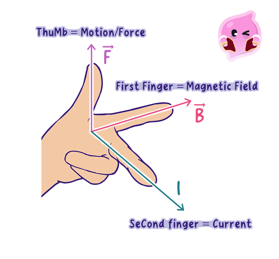
Fleming's left-hand rule states that when the first finger, second finger and thumb of the left hand are held at right angles, the first finger gives the magnetic field direction, the second finger the conventional current direction and the thumb the direction of the force.
Mutually perpendicular
Three directions are mutually perpendicular when each one is at 90 degrees to both of the other two.
- The rule turns your left hand into a model of three directions at right angles to each other, so that knowing any two of them gives you the third.
- Hold out the thumb, first finger and second finger of the left hand so that all three are mutually perpendicular, each one at 90∘90^\circ90∘ to the other two, like the corner of a box.
- Each digit then stands for one quantity:
- First finger gives the direction of the magnetic field, taken from north to south
- Second finger gives the direction of the conventional current, from positive to negative round the circuit
- ThuMb gives the direction of the force on the conductor, which is also the direction it moves in
- The capital letters give the memory aid: First finger for Field, seCond finger for Current, thuMb for Motion.
- The rule works because the force in the motor effect always acts at right angles to both the field and the current, so the three directions really do form the corner of a box.
- It applies only when the field and the current are themselves at right angles to each other. A conductor lying along the field lines has no force on it, and the rule cannot be set up.
- It is the left hand for the motor effect. The right hand belongs to the grip rule for the field around a current-carrying wire, and mixing the two hands gives an answer that is exactly backwards.
Using the rule
- Work through the same four steps every time, in this order:
- Read the field direction off the diagram, remembering that it runs from the north pole to the south pole.
- Read the current direction off the diagram, checking that it is conventional current and not electron flow.
- Point the first finger along the field, then rotate the whole hand about that finger until the second finger lies along the current.
- Read the force direction off the thumb.
- The rule can be run in any order. If the question gives the force and the field, set the thumb and first finger to match and the second finger then reveals the current direction.
- Reversing the current alone reverses the force, reversing the field alone reverses the force, and reversing both leaves the force pointing the way it did to begin with.
- Conventional current runs from the positive terminal round the external circuit to the negative terminal. Electrons in a metal drift the opposite way, so using electron flow gives a force in exactly the wrong direction.
- Do the hand movement physically rather than in your head. Turning your wrist and elbow to line the fingers up with the page is what makes the answer reliable.
- Keep the first finger fixed on the field while you rotate, because moving it as well is the commonest way of arriving at a wrong answer.
Dots and crosses on diagrams
- A flat diagram has to show directions that point straight into or straight out of the paper, and two symbols are used for this.
- A dot means the direction is out of the page, towards you. Picture the sharp point of an arrow flying straight at your eye.
- A cross means the direction is into the page, away from you. Picture the crossed flights at the tail of an arrow disappearing into the distance.
- Either symbol can stand for the field or for the current, so read the label on the diagram rather than assuming which one it is.
- A grid of crosses drawn over a whole region usually shows a uniform magnetic field directed into the page.
- To use the rule with one of these, turn your hand so that the matching finger points at the page or straight back towards your own face, and let your wrist take whatever position it needs.
- Never force your palm to stay flat against the desk. The hand has to be free to twist, and the answer is often uncomfortable to hold.
Finding the direction of the force
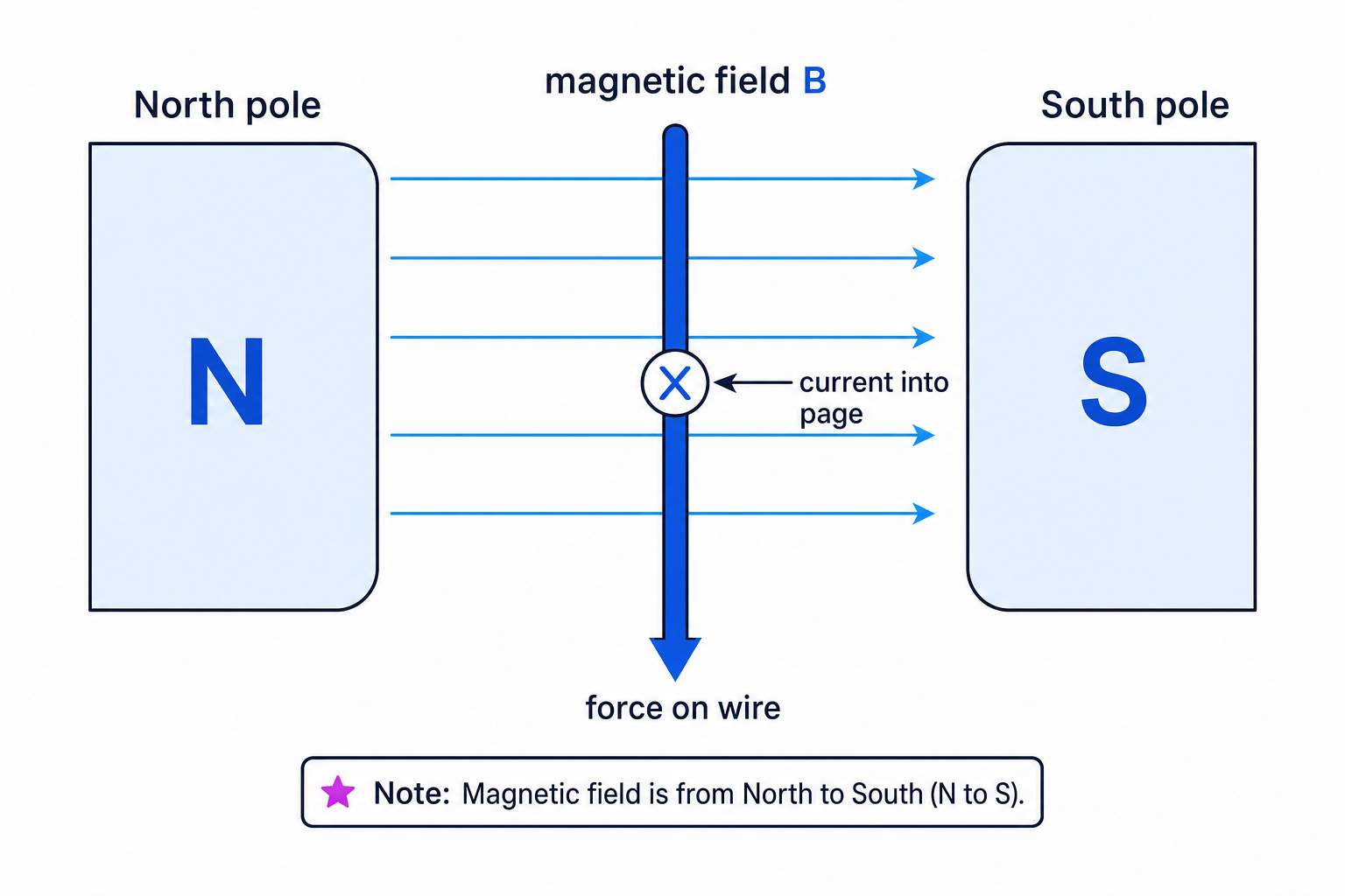
- A straight conductor carries conventional current into the page, shown by a cross, and it sits in a magnetic field that runs from left to right across the page.
- Choose the left hand, because this is the motor effect.
- Point the first finger to the right, matching the field direction shown on the diagram.
- Rotate the hand about that finger until the second finger points away from you, into the page, matching the cross.
- The thumb is now pointing down the page, so the force on the conductor acts downwards.
- Changing the cross to a dot, so the current now comes out of the page, reverses the current alone and the force becomes upwards.
Applying the rule in the exam
- Label the diagram before you touch your hand. Write F beside the field arrow and I beside the current arrow so that the two given directions cannot be swapped by mistake.
- Check the poles on the magnet and draw the field arrow yourself if the paper has not drawn one, always from north to south.
- Name the rule in your written answer, then give the direction, for example that Fleming's left-hand rule shows the force acts into the page.
- Answer with a direction the examiner can mark, such as upwards, to the left or out of the page, rather than a vague phrase like away from the magnet.
- If the question shows a circuit rather than an arrow, trace the path from the positive terminal of the supply to find which way the conventional current runs through the conductor.
- Do not use your right hand. The motor effect needs the left hand, and the right hand is for the grip rule.
- Do not put electron flow on the second finger. The rule uses conventional current, which runs the opposite way to the electrons in a metal.
- Do not swap the first finger and the thumb. The first finger is the field and the thumb is the force.
- Do not read a dot as into the page. A dot is the point of the arrow coming out at you.
- Do not apply the rule when the current runs along the field lines, because there is no force to find in that case.
- State which hand is used for Fleming's left-hand rule and which quantity each digit represents.
- Explain what mutually perpendicular means and why the rule requires it.
- State which current direction must be used and how it compares with the direction electrons move in a metal.
- Give the meaning of a dot and of a cross on a direction diagram.
- A field points to the left and the conventional current points out of the page. Determine the direction of the force.
- State what happens to the force when both the current and the magnetic field are reversed.
12.3.3 Force on a conductor
Magnetic flux density
Magnetic flux density
Magnetic flux density is a measure of the strength of a magnetic field, equal to the force per unit current per unit length acting on a conductor placed at right angles to the field.
Tesla
The tesla is the unit of magnetic flux density, equal to one newton per ampere metre.
- A field-line diagram shows where a field is stronger, but it gives no number. Magnetic flux density, given the symbol BBB, is the measured quantity that puts a value on that strength.
- The name comes from the field-line picture. A field with a high flux density has many field lines packed through each square metre, which is exactly what closely spaced lines represent.
- Its unit is the tesla, symbol T\text{T}T, which can also be written as the newton per ampere metre: 1 T=1 N/(A m)1\ \text{T} = 1\ \text{N}/(\text{A}\,\text{m})1 T=1 N/(Am)
- That second form is worth reading as a sentence. A field of 1 T1\ \text{T}1 T pushes on a 1 m1\ \text{m}1 m length of conductor carrying 1 A1\ \text{A}1 A with a force of 1 N1\ \text{N}1 N.
- One tesla is a very strong field. The Earth's field is roughly 0.00005 T0.00005\ \text{T}0.00005 T, a school horseshoe magnet gives about 0.1 T0.1\ \text{T}0.1 T, and a hospital scanner magnet reaches a few tesla.
- Magnetic flux density is not a force and not an energy. It measures the field itself, and a force only appears once a current is put into that field.
The force equation
- For a conductor lying at right angles to a magnetic field, the force on it is given by: F=BIlF = BIlF=BIl
- In this equation:
- FFF is the force on the conductor, in newtons, N\text{N}N
- BBB is the magnetic flux density, in tesla, T\text{T}T
- III is the current in the conductor, in amperes, A\text{A}A
- lll is the length of conductor inside the field, in metres, m\text{m}m
- The symbol lll is a lower-case letter L, not the digit 111. Write it clearly, because a badly formed lll costs marks in a substitution line.
- All three quantities are multiplied together, so each one is directly proportional to the force while the other two are held constant.
- Doubling any one of BBB, III or lll doubles the force. Doubling two of them at once multiplies the force by four.
- The two rearranged forms you may need are: B=FIlI=FBll=FBIB = \dfrac{F}{Il} \qquad I = \dfrac{F}{Bl} \qquad l = \dfrac{F}{BI}B=IlFI=BlFl=BIF
- The equation applies only when the conductor is at right angles to the field. A conductor set at some other angle feels a smaller force, and one lying along the field feels none.
- Only the length of conductor actually inside the field goes into lll. A 60 cm60\ \text{cm}60 cm wire passing through a magnet with 4 cm4\ \text{cm}4 cm pole faces contributes only 0.04 m0.04\ \text{m}0.04 m.
- Every length must be converted to metres before substituting, so 4 cm4\ \text{cm}4 cm becomes 0.04 m0.04\ \text{m}0.04 m and 85 mm85\ \text{mm}85 mm becomes 0.085 m0.085\ \text{m}0.085 m.
- The equation gives the size of the force only. Its direction is a separate question, answered by a hand rule rather than by the arithmetic.
Calculating the force on a wire
- A wire carries a current of 3.0 A3.0\ \text{A}3.0 A. A 0.40 m0.40\ \text{m}0.40 m length of it lies at right angles to a field of magnetic flux density 0.25 T0.25\ \text{T}0.25 T.
- The force is the unknown, so the equation is used as it stands.
- F=BIlF = BIlF=BIl
- Every quantity is already in SI units, so the values can be substituted directly.
- F=0.25×3.0×0.40F = 0.25 \times 3.0 \times 0.40F=0.25×3.0×0.40
- F=0.30 NF = 0.30\ \text{N}F=0.30 N
- The force on the wire is 0.30 N0.30\ \text{N}0.30 N, which is roughly the weight of a 30 g30\ \text{g}30 g mass.
Rearranging to find flux density
- A 0.20 m0.20\ \text{m}0.20 m length of wire carrying 4.0 A4.0\ \text{A}4.0 A at right angles to a field experiences a force of 0.48 N0.48\ \text{N}0.48 N.
- BBB is the unknown, so start from the equation and rearrange before substituting.
- F=BIlsoB=FIlF = BIl \qquad \text{so} \qquad B = \dfrac{F}{Il}F=BIlsoB=IlF
- B=0.484.0×0.20B = \dfrac{0.48}{4.0 \times 0.20}B=4.0×0.200.48
- B=0.480.80=0.60 TB = \dfrac{0.48}{0.80} = 0.60\ \text{T}B=0.800.48=0.60 T
- The magnetic flux density is 0.60 T0.60\ \text{T}0.60 T.
Using only the length inside the field
- A 75 cm75\ \text{cm}75 cm wire passes through the gap of a magnet whose pole faces are 5.0 cm5.0\ \text{cm}5.0 cm long. The flux density in the gap is 0.080 T0.080\ \text{T}0.080 T and the current is 2.5 A2.5\ \text{A}2.5 A.
- Only the part of the wire inside the field is pushed, so lll is the length of the pole faces and not the length of the wire.
- l=5.0 cm=0.050 ml = 5.0\ \text{cm} = 0.050\ \text{m}l=5.0 cm=0.050 m
- F=BIl=0.080×2.5×0.050F = BIl = 0.080 \times 2.5 \times 0.050F=BIl=0.080×2.5×0.050
- F=0.010 NF = 0.010\ \text{N}F=0.010 N
- Using the full 0.75 m0.75\ \text{m}0.75 m would have given 0.15 N0.15\ \text{N}0.15 N, fifteen times too large, which is why the length inside the field has to be identified first.
Measuring the force on a current-carrying conductor
- Aim: to measure the force on a conductor in a magnetic field, to show that the force is directly proportional to the current, and to use the results to find the magnetic flux density between the poles.
- Apparatus: a digital top-pan balance reading to 0.01 g0.01\ \text{g}0.01 g, two slab magnets on a steel yoke, a stiff copper wire bent into a rigid rectangle, a clamp stand, a low-voltage direct current supply, a rheostat, an ammeter, a switch, a 30 cm30\ \text{cm}30 cm ruler and connecting leads.
- Variables: the current is the independent variable, the change in the balance reading is the dependent variable, and the magnets, the length of wire in the field, the position of the wire in the gap and its right-angled orientation are all kept the same.
- Method, setting up:
- Stand the yoke and magnets on the balance pan so that the two pole faces face each other across a horizontal gap, and measure the length of the pole faces with the ruler.
- Clamp the wire rectangle so that its lower horizontal section hangs in the middle of the gap, at right angles to the field and touching nothing.
- Check by eye and with the ruler that the wire is horizontal and centred, because a tilted wire produces a sideways force the balance cannot register.
- Connect the wire in series with the switch, ammeter, rheostat and supply, keeping the leads slack so they cannot press on the magnets.
- Zero the balance with the magnets in place and the switch open, so the reading measures only the extra force produced by the current.
- Method, taking readings:
- Close the switch, set the current to 1.0 A1.0\ \text{A}1.0 A with the rheostat, read the balance, then open the switch again.
- Check that the balance returns to zero each time. If it does not, the wire is touching the magnets or the leads are pulling on the pan.
- Repeat for currents of 2.0 A2.0\ \text{A}2.0 A, 3.0 A3.0\ \text{A}3.0 A, 4.0 A4.0\ \text{A}4.0 A and 5.0 A5.0\ \text{A}5.0 A, taking three readings at each current and calculating a mean.
- Reverse the supply connections and repeat one reading. The balance reading changes sign, confirming that the direction of the force follows the direction of the current.
- Processing: convert each mean reading in grams to a force using F=mgF = mgF=mg with g=10 N/kgg = 10\ \text{N/kg}g=10 N/kg, so a reading of 0.35 g0.35\ \text{g}0.35 g gives F=0.00035×10=0.0035 NF = 0.00035 \times 10 = 0.0035\ \text{N}F=0.00035×10=0.0035 N.
- Analysis: plot FFF against III. A straight line through the origin shows that FFF is directly proportional to III, and comparing F=BIlF = BIlF=BIl with y=mxy = mxy=mx shows that the gradient equals BlBlBl, so BBB is found by dividing the gradient by the measured length.
- Expected pattern: the balance reading rises steadily with current, the graph is a straight line through the origin, and a typical pair of school slab magnets gives a flux density of the order of 0.1 T0.1\ \text{T}0.1 T.
- Watch out: forgetting to zero the balance with the magnets already on the pan, a wire that touches the poles, stiff leads that lift or press the assembly, measuring the whole wire instead of the length in the gap, and the current drifting downwards as the wire warms up.
- Safety: the wire heats quickly at several amperes, so close the switch only for as long as it takes to read the balance, keep the rheostat in circuit, and handle the slab magnets carefully because they snap together hard enough to trap fingers.
Setting out a force calculation
- Write F=BIlF = BIlF=BIl on its own line first. The selection mark is available even if the arithmetic afterwards goes wrong.
- List the values with their units before substituting, and do any centimetre to metre conversion on that list rather than in your head.
- Rearrange the equation before you put numbers in, not after. Substituting first and then trying to unpick the arithmetic is where most working goes wrong.
- Give the answer to the same number of significant figures as the data and always attach a unit: N\text{N}N for force, T\text{T}T for flux density, A\text{A}A for current and m\text{m}m for length.
- Use the phrase directly proportional only when a graph is a straight line through the origin, and quote the gradient as BlBlBl when asked to find BBB from one.
- Do not substitute a length in centimetres or millimetres. Convert to metres first.
- Do not use the total length of the wire when only part of it lies in the field. Use the length inside the field.
- Do not give the force in joules or watts. Force is measured in newtons, N\text{N}N.
- Do not apply this equation when the conductor is not at right angles to the field, since it holds only in that case.
- Do not treat BBB as a force. It measures the strength of the field, and the force also depends on the current and the length.
- State what magnetic flux density measures and give its unit in both accepted forms.
- Write down the equation for the force on a conductor at right angles to a magnetic field and give the unit of each quantity.
- Calculate the force on a 0.15 m0.15\ \text{m}0.15 m length of wire carrying 6.0 A6.0\ \text{A}6.0 A at right angles to a field of 0.20 T0.20\ \text{T}0.20 T.
- Explain what happens to the force when the current is trebled and the length is halved.
- State which length must be used for lll when a long wire passes through a short magnet.
- Describe how a graph of force against current can be used to find the magnetic flux density.
12.3.4 Electric motors
How a motor turns
Electric motor
An electric motor is a device that uses the forces on current-carrying conductors in a magnetic field to make a coil rotate.
Turning effect
A turning effect is the rotation produced when forces act on an object in such a way that they twist it about an axis rather than push it in a straight line.
- A simple motor is built from a rectangular coil of wire mounted on an axle so that it can spin, with the coil sitting in the field between the poles of a permanent magnet.
- Current is fed in at one side of the coil and leaves at the other, so the current travels all the way round the loop.
- Because the current goes round a loop, it runs along one long side of the coil in one direction and back along the other long side in the opposite direction. This single fact is what makes a motor work.
- Both long sides lie across the same magnetic field, so both experience a force. The field is the same for both, but the current directions are opposite, so the two forces point in opposite directions.
- One long side is pushed upwards while the other is pushed downwards, and each force acts at a distance from the axle.
- A pair of equal forces acting in opposite directions on opposite sides of an axle does not push the coil anywhere. It twists the coil instead, producing a turning effect, and the coil rotates.
- The short sides of the coil run along the field rather than across it, so they contribute no useful force and can be ignored in the explanation.
- Reversing the current alone reverses both forces and so reverses the direction of rotation. Reversing the magnetic field alone does the same. Reversing both together leaves the motor spinning the way it did before.
- Energy is transferred electrically from the supply to the kinetic energy store of the rotating coil, because the current-carrying sides are pushed by the magnetic field.
A motor rotates because the currents in the two sides of the coil are in opposite directions, so the forces on those sides are in opposite directions and produce a turning effect on the coil.
Keeping the coil turning
Split-ring commutator
A split-ring commutator is a rotating contact divided into two halves that reverses the current in the coil of a direct current motor every half turn.
- A coil connected straight to a battery would not keep spinning. It would turn half a revolution and then stall.
- The reason is that after half a turn the two sides have swapped places. The side that was on the left is now on the right, but the force on it still points the same way as before.
- The turning effect would then act the wrong way round, pushing the coil back towards where it came from, so it would rock to and fro and settle.
- A split-ring commutator solves this. It is a metal ring cut into two halves, mounted on the axle and turning with the coil, with each half connected to one end of the coil.
- Two fixed carbon brushes press against the ring and carry the current in from the supply while the ring spins past them.
- Every half turn, the gaps in the ring pass the brushes and each half of the ring meets the opposite brush, so the current through the coil is reversed.
- Reversing the current reverses both forces at exactly the moment the sides have swapped places, so the turning effect keeps acting the same way round and the coil carries on rotating.
- The switching is automatic and mechanical. Nothing in the circuit has to be operated by hand, because the commutator turns with the coil and reverses the current at the right instant on its own.
- The point worth writing in an answer is not the construction of the ring. It is that the current is reversed every half turn so that the coil keeps turning in the same direction.
Making a motor turn faster
- Increasing the current in the coil increases the force on each side, so the turning effect and the rotation rate both rise.
- Using stronger magnets raises the magnetic flux density in the gap, which again increases the force on each side of the coil.
- Adding more turns to the coil puts more current-carrying wire in the field, so the forces add and the turning effect grows.
- Making the coil wider moves each force further from the axle, which increases the turning effect without changing the size of either force.
- Reducing friction at the bearings and keeping the coil light both help, because less of the turning effect is wasted overcoming resistive forces.
- These are the ideas behind real motors. A cordless drill draws a large current through many turns wound on an iron armature between strong magnets, while a model motor uses a small current and a light coil.
Rotation rates and unit conversions
- The speed of a motor is quoted as a rotation rate, the number of complete turns made in a given time.
- Manufacturers usually quote rotations per minute, while physics calculations need rotations per second, so a conversion is often the first step. 1 min=60 s1\ \text{min} = 60\ \text{s}1 min=60 s
- To go from rotations per minute to rotations per second, divide by 606060. To go the other way, multiply by 606060.
- The time for one rotation is the reciprocal of the rate in rotations per second: t=1nt = \dfrac{1}{n}t=n1
- where ttt is the time for one rotation in seconds and nnn is the rotation rate in rotations per second.
- Rotation rate and the time for one rotation are inverses of each other, so a faster motor has a shorter time per rotation.
- Read the unit carefully. A rate of 60 rotations/s60\ \text{rotations/s}60 rotations/s means sixty turns every second, not sixty seconds for one turn.
Converting a rotation rate
- A small electric motor is quoted as running at 3600 rotations/min3600\ \text{rotations/min}3600 rotations/min. Its rate in rotations per second and the time for one rotation are both required.
- There are 60 s60\ \text{s}60 s in a minute, so divide the quoted rate by 606060.
- n=360060=60 rotations/sn = \dfrac{3600}{60} = 60\ \text{rotations/s}n=603600=60 rotations/s
- The motor therefore makes 606060 complete turns in every second.
- t=1n=160=0.0167 st = \dfrac{1}{n} = \dfrac{1}{60} = 0.0167\ \text{s}t=n1=601=0.0167 s
- To two significant figures the time for one rotation is 0.017 s0.017\ \text{s}0.017 s.
Using proportional reasoning on a motor
- A motor turns at 1200 rotations/min1200\ \text{rotations/min}1200 rotations/min when the current is 0.50 A0.50\ \text{A}0.50 A. The current is raised to 1.5 A1.5\ \text{A}1.5 A and the rotation rate is found to rise in the same ratio.
- Find the ratio of the two currents first.
- 1.50.50=3.0\dfrac{1.5}{0.50} = 3.00.501.5=3.0
- The current is three times larger, so the rotation rate is also three times larger.
- 1200×3.0=3600 rotations/min1200 \times 3.0 = 3600\ \text{rotations/min}1200×3.0=3600 rotations/min
- Converting gives 360060=60 rotations/s\dfrac{3600}{60} = 60\ \text{rotations/s}603600=60 rotations/s, so the time for one rotation falls from 0.050 s0.050\ \text{s}0.050 s to 0.017 s0.017\ \text{s}0.017 s.
Constructing a simple electric motor
- Aim: to build a working coil motor, to show that the forces on the two sides of the coil produce rotation, and to test how the current, the magnets and the number of turns affect how fast it spins.
- Apparatus: about 1 m1\ \text{m}1 m of enamelled copper wire, a cylindrical former such as a battery to wind the coil on, two paper clips bent into cradles, a wooden block or cork base, two strong slab or neodymium magnets, a 1.5 V1.5\ \text{V}1.5 V cell in a holder or a low-voltage supply, a rheostat, an ammeter, a switch, fine sandpaper, sticky tape and a stopwatch.
- Variables: the current, the strength of the magnets or the number of turns is the independent variable, the rotation rate is the dependent variable, and the coil, the base, the magnet positions and everything not being changed are kept the same.
- Method, building the coil:
- Wind about ten neat turns of enamelled wire round the former, then slide the coil off and leave a straight tail of a few centimetres projecting from each side along the same line.
- Loop each tail once through the coil to bind the turns together, so the coil holds its shape and stays balanced when it spins.
- Check that the two tails lie exactly opposite each other on a straight line through the middle of the coil, because a lopsided axle makes the motor wobble and stall.
- Method, making the contacts:
- Sand the enamel completely off one tail all the way round, so that this end always makes contact.
- Sand the enamel off only the upper half of the other tail, laying the wire flat and rubbing one side only.
- That half-stripped tail is a simple commutator. It carries current for half of every rotation and breaks the circuit for the other half, so the coil is only pushed while the push is in the useful direction.
- Tape the two paper-clip cradles to the base, rest the tails in them, and check that the coil spins freely by flicking it with a finger.
- Method, running and testing:
- Place the magnets directly below the coil, or one on each side of it, with unlike poles facing so that the field runs straight across the coil.
- Connect the paper clips in series with the switch, ammeter, rheostat and cell, close the switch and give the coil a gentle starting flick.
- Once it is spinning steadily, time 202020 rotations with the stopwatch and divide to find the time for one rotation, repeating three times for a mean.
- Change one variable at a time and repeat the timing: raise the current with the rheostat, then swap in stronger magnets, then rebuild the coil with twenty turns instead of ten.
- Finally turn the magnets over so the field is reversed, and note that the coil now spins the other way.
- Expected pattern: the coil spins steadily once started, it turns faster with a larger current, with stronger magnets and with more turns, and reversing either the current or the magnets reverses the direction of rotation.
- Processing: convert each mean time for one rotation into a rate in rotations per second using n=1tn = \dfrac{1}{t}n=t1, and then into rotations per minute by multiplying by 606060 so the results can be compared with a manufacturer's figure.
- Watch out: enamel left on the fully stripped tail so no current flows, both tails stripped all the way round so the coil rocks instead of turning, tails that are not in line, magnets too far away, and timing a single rotation instead of twenty, which makes reaction time a large share of the reading.
- Safety: the coil and the contacts get hot, so switch off between runs and never leave the circuit closed with the coil stationary. Keep fingers and hair clear of the spinning coil, take care with the sanded wire ends, and handle neodymium magnets carefully because they can pinch skin.
Explaining how a motor works
- This is usually an extended answer, so write it as a chain of short linked sentences: current flows in the coil, the coil is in a magnetic field, the two sides carry current in opposite directions, the forces on them act in opposite directions, and those forces produce a turning effect.
- The step most often missed is the one about opposite current directions. Without it the opposite forces have no cause and the explanation loses marks.
- Finish with the commutator sentence: it reverses the current every half turn so the coil keeps rotating in the same direction.
- Use the words current, magnetic field, force, opposite directions, turning effect and rotation, since these are the terms the mark scheme is written around.
- For a rate conversion, show the division by 606060 as a separate line of working so that the method mark stands even if the final figure is wrong.
- Do not confuse a motor with a generator. A motor takes a current and produces movement, while a generator takes movement and produces a potential difference.
- Do not write that the forces on the two sides cancel out. They act on opposite sides of the axle, so they twist the coil instead of cancelling.
- Do not say that electricity turns into force. Energy is transferred electrically to the kinetic energy store of the coil.
- Do not say the commutator reverses the magnetic field. It reverses the current in the coil, while the magnets stay exactly as they are.
- Do not read 60 rotations/s60\ \text{rotations/s}60 rotations/s as sixty seconds per rotation. It is sixty rotations in one second.
- Explain why the forces on the two long sides of a motor coil act in opposite directions.
- Explain how those two forces make the coil rotate rather than move in a straight line.
- Describe what a split-ring commutator does and explain why a motor needs one.
- Give three changes that would make a motor turn faster, with a reason for each.
- Convert a rotation rate of 2400 rotations/min2400\ \text{rotations/min}2400 rotations/min into rotations per second and find the time for one rotation.
- State what happens to the direction of rotation if both the current and the magnetic field are reversed.