12.2.1 Magnetic field around a current-carrying conductor
The magnetic effect of a current
Magnetic effect of a current
The magnetic effect of a current is the production of a magnetic field in the space around a conductor whenever there is a current in that conductor.
- A wire with no current in it has no magnetic field around it and has no effect at all on a nearby compass.
- Switch the current on and a magnetic field appears in the space around the wire. Switch it off and the field vanishes at once.
- The field is produced by the moving charges in the wire. Any moving charge is surrounded by a magnetic field, and a current is simply a great many charges moving together.
- The conductor itself is not made of a magnetic material. Copper is not attracted by a magnet, yet a copper wire carrying a current still produces a field.
- The current is not used up in making the field. The same current arrives back at the supply, and the field lasts exactly as long as the charge keeps flowing.
- This single fact is the root of the whole of electromagnetism. Every electromagnet, relay, loudspeaker and electric motor works because a current makes a magnetic field.
Showing the field around a straight conductor
- Aim: to show that a current in a long straight conductor produces a magnetic field, to find the shape and direction of that field, and to test how its strength depends on the current and on the distance from the wire.
- Apparatus: a thick insulated copper wire, a stiff sheet of white card with a hole punched at its centre, a retort stand and clamps to hold the card level, a low-voltage direct current power supply or battery pack, a rheostat, an ammeter, a switch, four or more plotting compasses, iron filings in a shaker, a ruler and connecting leads.
- Variables: the current and the distance from the wire are the independent variables, the deflection of the compass needle is the dependent variable, and the wire, its vertical alignment, the compasses used and the surroundings are all kept the same.
- Method, setting up:
- Thread the wire vertically through the hole in the card and clamp the card horizontally, so the wire passes through it at a right angle.
- Connect the wire in series with the switch, the ammeter, the rheostat and the supply, keeping the leads well away from the card so their own fields do not confuse the result.
- With the switch open, place four plotting compasses on the card at equal distances round the wire and note that every needle points the same way, along the Earth's field.
- Set the rheostat to its highest resistance before closing the switch, so the first current through the wire is small.
- Method, finding shape and direction:
- Close the switch briefly and watch the compasses. Each needle swings round until it lies at a tangent to a circle drawn round the wire.
- Record the direction of every needle by sketching it on the card, then read off whether the pattern runs clockwise or anticlockwise when viewed from above.
- Open the switch, swap the two leads at the supply so the current now flows the other way, close the switch again and record the new directions.
- Clear the compasses away, sprinkle iron filings thinly over the card, close the switch and tap the card gently. The filings settle into circles centred on the wire.
- Method, testing strength:
- Put one compass a fixed 2 cm2\ \text{cm}2 cm from the wire and record the angle its needle turns through for currents of 1 A1\ \text{A}1 A, 2 A2\ \text{A}2 A, 3 A3\ \text{A}3 A and 4 A4\ \text{A}4 A, set with the rheostat and read on the ammeter.
- Then hold the current steady and move the same compass to 1 cm1\ \text{cm}1 cm, 2 cm2\ \text{cm}2 cm, 4 cm4\ \text{cm}4 cm and 8 cm8\ \text{cm}8 cm from the wire, recording the deflection each time.
- Switch off between readings so that the wire does not heat up, and take three readings at each setting to find a mean.
- Expected pattern: the needles form circles round the wire, the whole pattern turns the other way when the current is reversed, larger currents give larger deflections, and the deflection falls off as the compass is moved away from the wire.
- Comparing the two detectors: iron filings give a sharper picture of the circular shape, but only the compasses show which way round the field points.
- Watch out: a sloping or sagging wire, leaving the current on so long that the wire gets hot and the reading drifts, iron or steel under the bench, connecting leads lying close to the card, and forgetting that the Earth's field is still acting on every compass.
- Safety: keep the current low and switch on only in short bursts, since a thick wire carrying several amperes becomes hot enough to burn. Never connect the wire straight across the supply without the rheostat, and keep iron filings away from eyes.
Shape and direction of the field
Conventional current
Conventional current is the direction of flow of charge taken to be from the positive terminal of the supply to the negative terminal around the external circuit.
Right-hand grip rule
The right-hand grip rule states that if the right thumb points along the conventional current in a straight conductor, the curled fingers give the direction of the circular magnetic field lines around it.
- The magnetic field around a long straight conductor is a set of concentric circles lying in planes at right angles to the wire, with the wire itself at the centre of every circle.
- Concentric means the circles share the same centre. They do not overlap and they do not cross.
- The field goes around the wire, not along it. The current runs along the wire while the field wraps round it, and the two directions are at right angles.
- This field has no north pole and no south pole. The lines are closed loops that never begin or end anywhere, which is why a straight wire cannot be labelled N and S.
- The way round the circles run is decided by the direction of the conventional current, and it is found with the right-hand grip rule.
- To use the rule, grip the wire in your right hand as though holding a pen:
- point the thumb along the wire in the direction of the conventional current
- the curled fingers then sweep round the wire the same way as the magnetic field lines
- The rule uses the right hand and it uses conventional current, which flows from the positive terminal of the supply round to the negative terminal. Electrons in the metal drift the opposite way.
- Reversing the current reverses the field. Every circle keeps its shape and its size, but every arrow on it turns the other way round.
- In a diagram of a vertical wire seen from above, a current flowing upwards out of the page gives anticlockwise circles, and a current flowing downwards into the page gives clockwise circles.
Finding which way the field circles
- A vertical wire passes through a horizontal card and the conventional current in it flows upwards. The card is viewed from above.
- Grip the wire with the right hand and point the thumb straight up, matching the direction of the conventional current.
- Looking down on your own hand from above, the curled fingers sweep round anticlockwise.
- The field lines on the card are therefore circles centred on the wire with their arrows pointing anticlockwise.
- A compass placed to the north of the wire on the card would settle pointing due west, because west is the tangent direction there.
- If the supply leads are swapped so the current flows downwards, the same reasoning gives clockwise circles and that compass swings right round to point due east.
How strong the field is
- Two things decide the strength of the field around a long straight conductor: the size of the current and the distance from the conductor.
- A larger current gives a stronger field, because more charge is flowing past each point every second.
- A greater distance from the wire gives a weaker field, so the field is strongest right at the surface of the conductor and fades away as you move outwards.
- On a field-line diagram this is drawn by spacing the circles unevenly: they are packed tightly close to the wire and drawn further and further apart towards the outside.
- There is no equation to learn or use for this field. What is assessed is the qualitative link: more current means a stronger field, more distance means a weaker one.
- The field around a single straight wire is weak. A wire carrying a few amperes barely disturbs a compass held a hand's width away, which is why bigger effects need the current concentrated into a coil.
Describing the field around a wire
- A describe question here is normally worth three marks, one each for the circular shape, the link between field direction and current direction, and the effect of current or distance on strength.
- Use the word concentric and say the circles are centred on the wire, because circles alone leaves the position of the centre unstated.
- In a method question, the observation that scores is the change when the switch is closed, so describe what the compasses do before as well as after.
- Name plotting compasses whenever the question asks about direction, and iron filings only when it asks about shape.
- The mark most often dropped is the reversal one. Add a sentence saying that swapping the supply connections reverses the field direction, since that shows the link rather than just stating it.
- Do not draw the field lines running along the wire. The current runs along it and the field circles around it.
- Do not label a north pole and a south pole on a straight current-carrying wire. Its field lines are closed loops with no poles.
- Do not use your left hand for the grip rule, and do not use the direction electrons drift. The rule needs the right hand and conventional current.
- Do not write that the current is used up producing the field, or that only a wire made of iron would work.
- Describe an experiment that shows a current in a straight wire produces a magnetic field.
- State the shape of the magnetic field around a long straight current-carrying conductor.
- Explain how the right-hand grip rule is used to find the direction of that field.
- State what happens to the field when the direction of the current is reversed.
- Give the two factors that determine how strong the field is, and say how each one affects it.
- Explain why plotting compasses are better than iron filings for showing the direction of this field.
12.2.2 Solenoids and electromagnets
Solenoids and electromagnets
Solenoid
A solenoid is a long coil of insulated wire that produces a magnetic field when there is a current in the wire.
Electromagnet
An electromagnet is a magnet made by passing a current through a coil of wire, which is magnetic only while the current flows.
- A solenoid is made by winding a single length of insulated wire into many closely packed loops, each loop being called a turn.
- The wire is insulated so that the current is forced to travel all the way round every turn instead of taking a short cut where the turns touch.
- The same current passes through every turn in the same direction, one after another, because the coil is a single unbroken wire in series with the supply.
- Each turn on its own is a short piece of current-carrying conductor, and so each one produces its own circular magnetic field.
- The field of the whole solenoid is the combination of all these separate fields, added together point by point through the space in and around the coil.
- The result looks like the field of a bar magnet. The field lines emerge from one end of the solenoid, loop round the outside and return at the other end, so a solenoid has a north end and a south end.
- The important difference from a bar magnet is that a solenoid can be switched off. Break the circuit and the field disappears instantly, which is what makes an electromagnet so useful.
- Reversing the current swaps the two ends over, so the end that was a north end becomes a south end. A permanent magnet cannot be reversed this way.
The field inside the solenoid
- Along the axis running through the middle of the coil, the field contributed by every single turn points the same way, straight down the centre of the solenoid.
- Because the contributions all point the same way, they add together. Two hundred turns each adding their share build a field far stronger than any one turn could produce alone.
- The field inside is also almost uniform, meaning it has nearly the same strength and the same direction everywhere in the central region of the coil.
- It works out this way because every turn is identical and evenly spaced, so wherever you stand inside the coil the arrangement of turns around you looks much the same.
- On a diagram the inside field is drawn as lines that are:
- straight and parallel to the axis of the coil
- evenly spaced across the width of the coil
- packed much more closely than the lines drawn outside, showing the much stronger field
- The word almost matters. Right at the two open ends the lines begin to fan out, so the field is only truly even well inside a long coil.
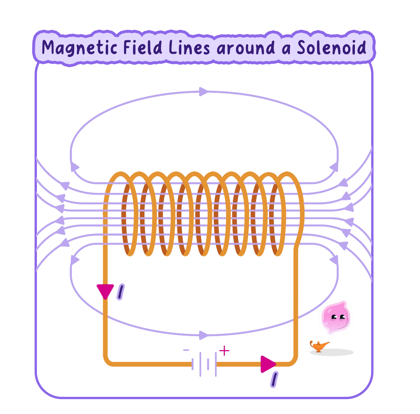
The field outside the solenoid
- Outside the coil the geometry is different. A point out there sits on the far side of some turns and near the near side of others, so the fields reaching it point in a range of different directions.
- Because those directions oppose one another, the contributions partly cancel instead of adding, so what is left over is small.
- The field outside is therefore much weaker than the field inside, and it is drawn with widely spaced lines that spread out around the coil.
- Weaker does not mean zero. The outside field is real, it is the part that reaches out to attract a nail, and it is what a plotting compass held beside the coil responds to.
- The same field lines that run down the inside of the coil come back round the outside, so the loops are continuous. Crowding them into the narrow inside and spreading them over the wide outside is exactly what makes one region strong and the other weak.
Inside a solenoid the fields from the individual turns act in the same direction and add together to give a strong, almost uniform field along the centre, while outside they act in opposing directions and cancel to give a weaker field.
Making an electromagnet stronger
- Increasing the current strengthens the field, because every turn then contributes a larger share.
- Increasing the number of turns strengthens the field, because there are more contributions to add together in the same length of coil.
- Adding an iron core down the middle strengthens the field greatly. The coil's field magnetises the iron, and the magnetised iron then produces a field of its own that adds to the coil's.
- The core must be iron rather than steel, so that it loses its magnetism the moment the current is switched off and the electromagnet truly releases its load.
- Winding the turns closer together also helps, because packing more turns into each centimetre of coil raises the field along the axis.
- These design choices show up in everyday devices: a scrapyard crane magnet uses a very large current and a heavy iron core, while a doorbell uses a small current and many fine turns.
Comparing two electromagnet designs
- Coil A has 505050 turns wound on a plastic tube and carries a current of 2.0 A2.0\ \text{A}2.0 A. Coil B has 200200200 turns of the same wire wound over the same length on an iron rod and carries a current of 2.0 A2.0\ \text{A}2.0 A.
- The current is identical in the two coils, so any difference must come from the turns or from the core.
- Coil B has four times as many turns in the same length, so four times as many contributions add together along its axis.
- Coil B also has an iron core. The coil's field magnetises the iron, and the induced magnetism of the core adds a further field of its own.
- Coil B therefore produces a much stronger field and picks up far more paper clips, and the core effect alone accounts for most of that increase.
- Switching both coils off leaves neither of them magnetic, because iron keeps almost no magnetism once the magnetising field has gone.
Investigating the strength of an electromagnet
- Aim: to find how the strength of an electromagnet depends on the current in the coil and on the number of turns, and to compare the field inside and outside a solenoid.
- Apparatus: about 2 m2\ \text{m}2 m of insulated copper wire, a large iron nail or soft iron rod, a low-voltage direct current supply, a rheostat, an ammeter, a switch, a box of small steel paper clips, a plotting compass, a card sleeve, iron filings and connecting leads.
- Variables: the current or the number of turns is the independent variable, the number of paper clips lifted is the dependent variable, and the core, the wire, the clips and whichever of current and turns is not being changed are all kept the same.
- Method, building the electromagnet:
- Wind 202020 neat turns of insulated wire around the iron nail, keeping the turns touching and all wound the same way round, and leave long tails at both ends.
- Scrape the enamel off the two tails and connect them in series with the switch, ammeter, rheostat and supply.
- Set the rheostat to its maximum resistance so that the first current is small, and check that the ammeter reads before any clips are lifted.
- Method, changing the current:
- Close the switch, set the current to 0.5 A0.5\ \text{A}0.5 A, dip the end of the nail into the pile of paper clips and lift it out slowly and vertically.
- Count the clips hanging from the nail, then open the switch over the pile so that every clip drops off and can be counted as a check.
- Repeat for currents of 1.0 A1.0\ \text{A}1.0 A, 1.5 A1.5\ \text{A}1.5 A, 2.0 A2.0\ \text{A}2.0 A and 2.5 A2.5\ \text{A}2.5 A, taking three trials at each current and calculating a mean.
- Leave the switch open between readings so that the coil and the rheostat do not heat up, since a hot coil has a higher resistance and the current drifts downwards.
- Method, changing the turns:
- Fix the current at 1.5 A1.5\ \text{A}1.5 A using the rheostat, and check it after every change of coil because unwinding wire alters the resistance of the circuit.
- Repeat the clip count for coils of 202020, 404040, 606060, 808080 and 100100100 turns, winding each new coil over the same length of nail.
- Finally slide the coil off the nail and repeat one reading with no core at all, so the effect of the iron can be seen on its own.
- Method, showing the field pattern:
- Push the coil through a card sleeve, sprinkle iron filings on the card, close the switch and tap gently to reveal the pattern in and around the coil.
- Hold a plotting compass at each end of the coil in turn to identify which end is the north end, then reverse the supply leads and check that the ends have swapped.
- Expected pattern: the number of clips rises as the current rises and as the number of turns rises, the coil with the iron core lifts far more clips than the same coil without one, and the filings settle into dense straight lines through the middle of the coil with sparse looping lines outside.
- Processing: plot mean clips against current and mean clips against number of turns. Both graphs rise, and neither can be extended indefinitely because the iron core eventually reaches saturation and stops getting any more magnetic.
- Watch out: turns wound in opposite directions, which cancel rather than add; clips of mixed sizes; lifting the nail too quickly so clips shake off; leaving the current on so the coil overheats; and clips clinging to the nail from a previous reading because the iron was not fully demagnetised.
- Safety: the coil becomes hot, so keep currents modest and switch on only in short bursts, never connect the coil directly across the supply without the rheostat, take care with the sharp nail point, and pick up dropped clips at once.
Explaining the solenoid field
- This explanation is marked as a comparison, so a full answer has to deal with the inside and the outside, not just say that the field is strong.
- Start every answer from the individual turns. The examiner is looking for the idea that each turn produces its own field before anything is said about adding or cancelling.
- The four phrases that carry the marks are fields from individual turns add together, strong almost uniform field along the centre, fields cancel outside and weaker field outside.
- Include the reason for each half using the word because, since the marks are for the cause rather than the description.
- For a question about improving an electromagnet, give a change and its effect together, such as increasing the number of turns so that more fields add along the centre.
- Do not write that there is no field outside the solenoid. The outside field is weaker, not zero.
- Do not say the field inside is perfectly uniform. It is almost uniform, and it fans out near the open ends.
- Do not describe field lines as objects that push each other. They are a way of drawing a field, and it is the fields themselves that add and cancel.
- Do not suggest a steel core for an electromagnet that has to release its load, because steel stays magnetised after the current is switched off.
- Explain why the fields from the individual turns add together inside a solenoid.
- Describe the field lines drawn inside a solenoid and say what each feature represents.
- Explain why the field outside a solenoid is weaker than the field inside it.
- Give three changes that would make an electromagnet stronger, with a reason for each.
- State what happens to the north end of a solenoid when the current is reversed.
- Describe how you would show experimentally that more turns give a stronger electromagnet.
