10.1.1 Structure of the atom
The nuclear model
Atom
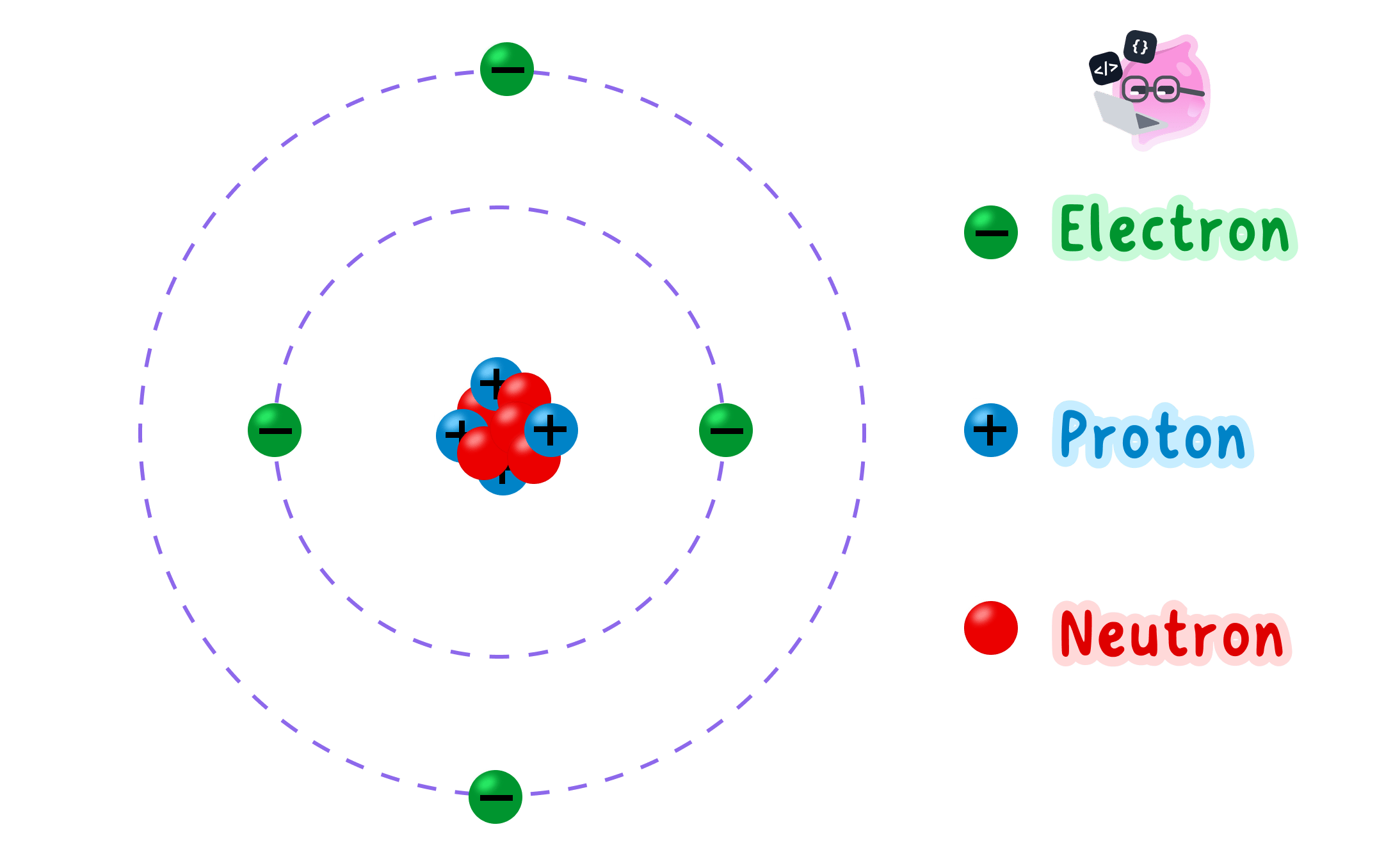
An atom is the smallest particle of an element, made of a central nucleus containing protons and neutrons with electrons arranged around it.
Nucleus (atom)
The nucleus is the small positively charged centre of an atom that contains the protons and neutrons and almost all of the atom's mass.
- In the nuclear model, every proton and every neutron in an atom is packed into a very small central nucleus, and the electrons are found in the space around that nucleus.
- Protons and neutrons are the only particles inside the nucleus, which is why they are together called nucleons.
- Electrons are never inside the nucleus. They move around it in shells, which are fixed regions at different distances from the centre.
- The electrons are held in place by the attraction between their negative charge and the positive charge of the nucleus, so the atom holds together without the electrons flying off.
- The three particles are not arranged evenly through the atom: the mass is concentrated at the centre while the volume is set by how far out the electron shells reach.
- Almost all of the inside of an atom is empty space. The electrons themselves are far too small to fill the region they move through.
Relative mass and charge
Relative mass
The relative mass of a particle is its mass compared with the mass of a proton, which is taken as 111.
Relative charge
The relative charge of a particle is its electric charge compared with the charge on a proton, which is taken as +1+1+1.
- A proton has a relative mass of 111 and a relative charge of +1+1+1.
- A neutron has a relative mass of 111 and a relative charge of 000, so it is uncharged.
- An electron has a relative mass of about 11836\frac{1}{1836}18361 and a relative charge of −1-1−1.
- Relative mass compares a particle with a proton, and relative charge compares a particle with the size of the charge on a proton. Both are ratios, so they are written as plain numbers.
- In actual units a proton has a mass of about 1.67×10⁻²⁷ kg1.67\times10^{-27}\ \text{kg}1.67×10⁻²⁷ kg while an electron has a mass of about 9.11×10⁻³¹ kg9.11\times10^{-31}\ \text{kg}9.11×10⁻³¹ kg, and dividing one by the other gives the factor of about 183618361836.
- The charge on an electron is exactly equal in size to the charge on a proton and opposite in sign, even though the two particles have hugely different masses.
- Because a neutron carries no charge, adding neutrons to a nucleus changes the mass of the atom but leaves its charge completely unchanged.
Relative mass and relative charge are comparisons rather than measurements, so they never carry a unit such as kg\text{kg}kg or C\text{C}C.
Where the mass sits
- The relative mass of a nucleus is the number of protons added to the number of neutrons, because each of those particles counts as 111.
- Each electron adds only about 11836\frac{1}{1836}18361 to the total, which is roughly 0.0005450.0005450.000545.
- Even in an atom with many electrons, their combined relative mass stays far below 111, so it never becomes a significant share of the total.
- Almost all of the mass of an atom is therefore in the nucleus, and for calculations at this level the mass of the electrons is treated as negligible.
- The nucleus is also extremely small, so it holds a large mass in a tiny volume and is by far the densest part of the atom.
- When the mass of an atom is quoted, that figure is effectively the mass of its protons and neutrons alone.
Mass carried by the electrons
- A lithium atom contains 333 protons, 444 neutrons and 333 electrons.
- The relative mass of the nucleus is 3+4=73+4=73+4=7, since each proton and each neutron counts as 111.
- The relative mass of the three electrons is 3×11836=1.63×10⁻³³\times\frac{1}{1836}=1.63\times10^{-3}3×18361=1.63×10⁻³.
- The total relative mass of the atom is 7+1.63×10−3=7.001637+1.63\times10^{-3}=7.001637+1.63×10−3=7.00163.
- The fraction of the mass carried by the electrons is 1.63×10−37.00163=2.3×10⁻⁴\frac{1.63\times10^{-3}}{7.00163}=2.3\times10^{-4}7.001631.63×10−3=2.3×10⁻⁴.
- That fraction is about 0.023%0.023\%0.023%, so the nucleus holds effectively all of the mass of the atom.
Why an atom is neutral
- Each proton contributes +1+1+1 and each neutron contributes 000, so the relative charge of a nucleus is simply the number of protons inside it.
- A nucleus is therefore always positively charged, and its charge grows as the number of protons grows.
- In a neutral atom the number of electrons is equal to the number of protons.
- Every +1+1+1 from a proton is then matched by a −1-1−1 from an electron, so the positive and negative charges cancel exactly.
- The total relative charge of a neutral atom is 000, which is what is meant by saying it has no overall charge.
- A carbon atom, for instance, has 666 protons giving +6+6+6 and 666 electrons giving −6-6−6, and +6−6=0+6-6=0+6−6=0.
- This cancelling depends only on the numbers of particles and their charges, not on their masses, so the very light electrons balance the much heavier protons perfectly.
- Do not place electrons inside the nucleus. Only protons and neutrons are found there.
- Do not state that an electron has zero mass. Its relative mass is about 11836\frac{1}{1836}18361, which is very small but not nothing.
- Do not write the relative charge of a proton as 1 C1\ \text{C}1 C, because relative charge has no unit.
- Do not say the nucleus is uncharged because it contains neutrons. The protons make it positive and the neutrons leave that charge unchanged.
- Do not confuse the two ideas of size: the nucleus carries nearly all of the mass but occupies almost none of the volume.
Size of the atom
- The radius of an atom is about 1×10⁻¹⁰ m1\times10^{-10}\ \text{m}1×10⁻¹⁰ m.
- The radius of a nucleus is about 1×10⁻¹⁵ m1\times10^{-15}\ \text{m}1×10⁻¹⁵ m, which is roughly 1100000\frac{1}{100000}1000001 of the radius of the whole atom.
- Dividing one radius by the other gives 1×10−101×10−15=1×10⁵\frac{1\times10^{-10}}{1\times10^{-15}}=1\times10^{5}1×10−151×10−10=1×10⁵, so the atom is about a hundred thousand times wider than its nucleus.
- Because volume depends on the cube of the radius, the nucleus occupies only about 1×10−151\times10^{-15}1×10⁻¹⁵ of the volume of the atom.
- On a scale where the nucleus is the size of a pea at the centre of a large sports stadium, the nearest electrons would be out at the seats.
- The atom is therefore mostly empty space, with all of its mass at the centre and all of its volume mapped out by the electron shells.
- In a metal the outermost electrons are held only weakly, so they break away from individual atoms and become free to move through the whole structure, and it is the movement of these free electrons that makes an electric current possible.
Describing atomic structure
- Name each particle, say where it is found, then give its relative mass and its relative charge, in that order.
- Give relative mass and relative charge as plain numbers such as 111, 000, +1+1+1 and −1-1−1, with no unit attached.
- Write atomic sizes in standard form, such as 1×10⁻¹⁰ m1\times10^{-10}\ \text{m}1×10⁻¹⁰ m for an atom, rather than as a long string of decimal places.
- To explain why an atom is neutral, state that the number of protons equals the number of electrons and that their charges are equal in size and opposite in sign.
- To explain why the mass is in the nucleus, compare the relative mass of 111 for a nucleon with the 11836\frac{1}{1836}18361 of an electron.
- State where protons, neutrons and electrons are found in an atom.
- Give the relative mass and relative charge of each of the three particles.
- Explain why almost all of the mass of an atom is in its nucleus.
- Explain why a neutral atom has no overall charge.
- Compare the radius of an atom with the radius of its nucleus.
10.1.2 Circuit diagrams and symbols
What a circuit diagram shows
Circuit diagram
A circuit diagram is a drawing of an electric circuit in which each component is shown by its standard symbol and the connecting wires are drawn as straight lines.
Component
A component is any single part of an electric circuit, such as a lamp, a resistor, a switch or a meter.
- A circuit diagram replaces a drawing of the real apparatus with an agreed symbol for each component, joined by straight lines that stand for the connecting wires.
- Every component has one standard symbol, so the same diagram can be read by anyone without a written explanation alongside it.
- A circuit diagram records how the components are connected to one another. It does not record where they sit on the bench, how long the leads are, or how large any object is.
- The diagram is never drawn to scale, so a small symbol may stand for a large piece of apparatus and a short straight line may stand for a long coiled lead.
Drawing conventions
- Draw every connecting wire as a straight line with a ruler, and turn every corner as a right angle rather than a curve.
- Bring each line squarely into the end of a symbol, so that it is obvious which two points of that symbol the wires are joined to.
- The circuit must form a complete loop with no gaps anywhere in the line, unless a switch has deliberately been drawn in its open position.
- A meeting point where three or more wires are joined is called a junction, and it is marked with a filled dot so that the join is unmistakable.
- Two lines that cross without a filled dot are read as not connected, so unnecessary crossings are best removed by redrawing the layout.
- No symbol is left with a line dangling from it, and no real component is given two symbols.
- Where labels are wanted, the name of the component is written beside its symbol and not inside it.
- A filled dot where lines meet means the wires are joined at that point.
- Two lines crossing with no dot means the wires simply pass over one another.
- Leaving the dot off a genuine junction changes the circuit that the diagram describes.
Cells and batteries
Cell
A cell is a single source of potential difference that uses a chemical reaction to push charge around a circuit.
Battery
A battery is two or more cells joined together in series so that their potential differences add.
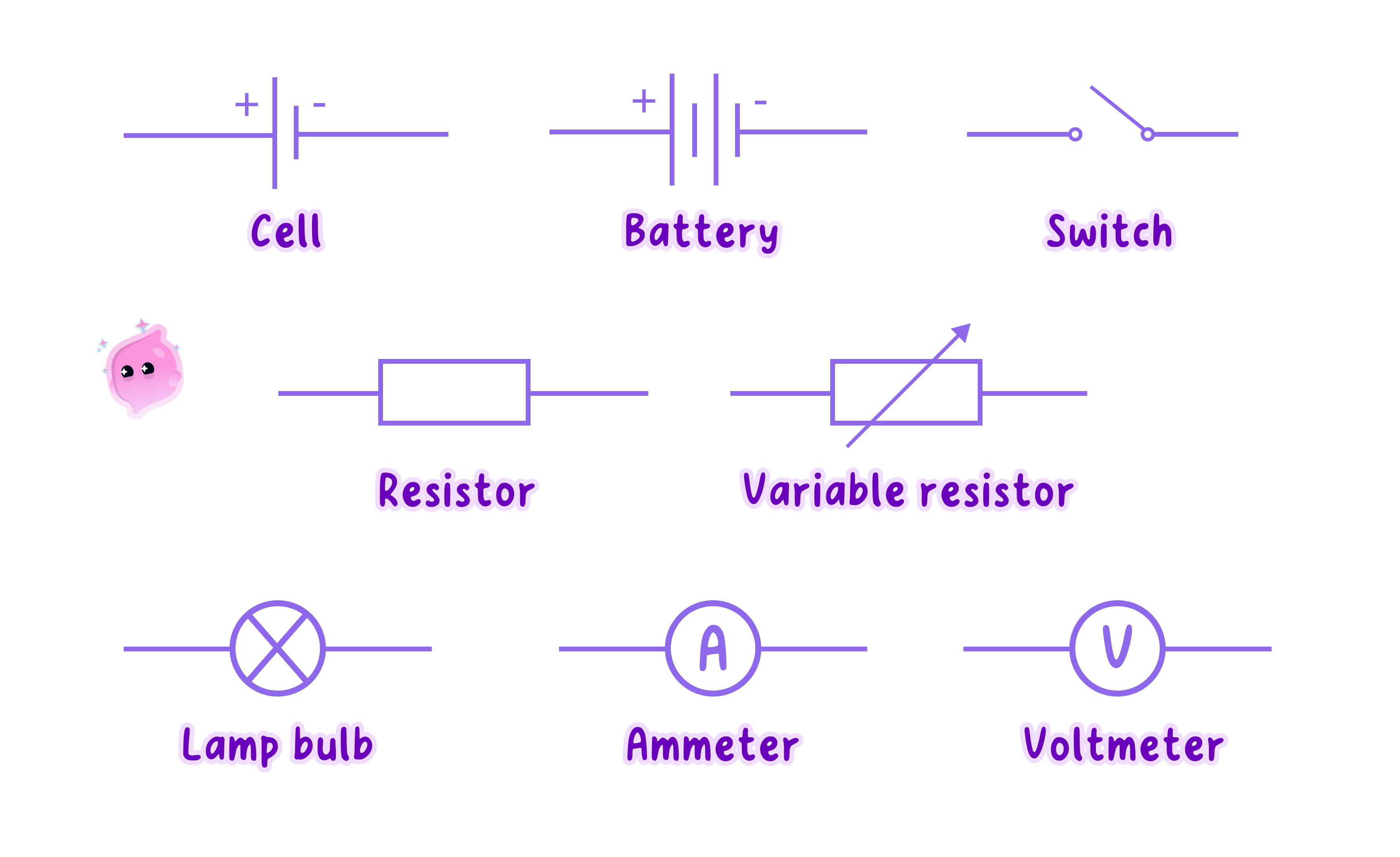
- The symbol for a cell is a pair of parallel lines drawn across a break in the wire: one long thin line and one short thick line.
- The long thin line stands for the positive terminal and the short thick line stands for the negative terminal.
- A battery is two or more cells joined end to end, so its symbol is simply the cell symbol repeated in a row with a small gap between each pair of lines.
- Every cell in a battery symbol faces the same way, with all of the long thin lines on the same side, because the cells are meant to push in the same direction round the loop.
- One cell drawn the wrong way round describes a different circuit from the one intended, so the orientation of the lines is part of the answer and not decoration.
In every cell and battery symbol the long thin line marks the positive terminal.
Symbols to recognise
- A switch is drawn as two contacts in a break in the line: it is open when the moving contact is lifted away from the second contact, and closed when it lies flat and bridges the gap.
- A filament lamp is a circle with a cross inside it, and a fixed resistor is a plain rectangle with nothing inside it.
- A variable resistor is the same rectangle with an arrow drawn diagonally across it, and a fuse is a rectangle with a line running through it from one side to the other.
- An ammeter is a circle containing the letter A\text{A}A and a voltmeter is a circle containing the letter V\text{V}V.
- A diode is a solid triangle pointing at a short bar, with the point of the triangle showing the single direction in which the diode allows charge through, and a light-emitting diode is that same symbol with two small arrows pointing away from it.
- A light-dependent resistor is a resistor rectangle inside a circle with two arrows pointing in towards it, and a thermistor is a resistor rectangle with a line drawn across it that bends upwards at one end.
- A motor is a circle containing the letter M\text{M}M and a generator is a circle containing the letter G\text{G}G.
- A loudspeaker is a small rectangle with a cone opening outwards from one side, and a thermocouple is drawn as two lines of different metals meeting at a single point.
Switches and meters
- A switch drawn in the single loop of a circuit controls the whole loop, because opening it breaks the only path the wires provide.
- An ammeter is always drawn as part of the loop itself, so the line runs into one side of the circle and out of the other side.
- A voltmeter is always drawn on its own short branch, with the line leaving the loop just before the component and rejoining it just after, so that the meter sits across that component.
- Drawn in that way, the voltmeter and the component enclose a small loop of their own on the page, which is how a reader recognises the connection at a glance.
- Do not draw an ammeter on a side branch. Its symbol belongs in the loop, with the line passing straight through it.
- Do not draw a voltmeter in the loop. Its symbol belongs on a branch across the named component.
- Do not leave a gap where the line should continue, because a gap describes a broken circuit rather than a tidy drawing.
- Do not treat two crossing lines as joined. Only a filled dot shows a junction.
- Do not sketch the real appearance of a component, such as a coil of wire in place of the plain rectangle of a fixed resistor.
From apparatus to diagram
- Begin by listing every real object shown in the photograph or named in the description, and write the symbol that stands for each one beside it.
- Choose one terminal of the supply and trace the leads by hand all the way round to the other terminal, noting each component in the order it is met.
- Draw the loop as a plain rectangle first, then place the symbols along its sides in that same order, spacing them out so each one is clear.
- Represent every lead, crocodile clip and terminal block as a plain straight line, since none of them has a symbol of its own.
- Finish by checking the finished drawing back against the list, so that no component has been left out and none has been invented.
Drawing a circuit accurately
- Use a ruler and a sharp pencil, and draw the wires as straight lines with right-angled corners.
- Check that the loop closes before moving on, since an accidental gap costs the mark even when every symbol is correct.
- Put a filled dot at every point where three or more wires meet.
- Show a switch in the position the question describes, open or closed, rather than choosing one at random.
- Where a meter is asked for, place the ammeter in the loop and the voltmeter across the component that the question names.
- Draw the symbols for a cell, a battery, a fixed resistor and a variable resistor.
- State which line of a cell symbol represents the positive terminal.
- Explain what a filled dot at a meeting point of wires tells the reader.
- Name the components whose symbols are circles containing A\text{A}A, V\text{V}V, M\text{M}M and G\text{G}G.
- Describe where an ammeter and a voltmeter are drawn in a circuit diagram.
10.1.3 Series and parallel circuits
Series circuits
Series circuit
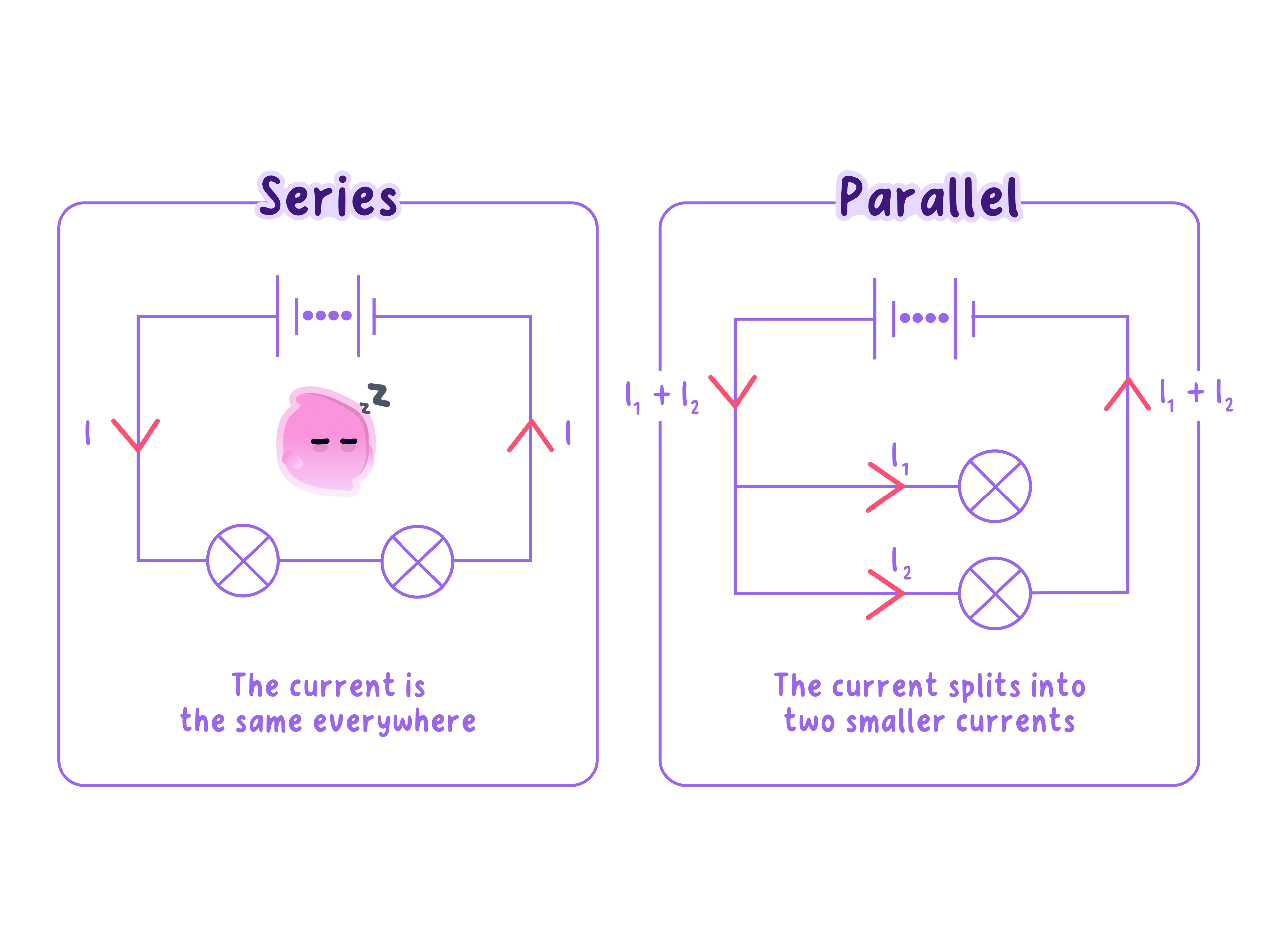
A series circuit is a circuit in which the components are joined one after another in a single loop, so there is only one path for the charge to follow.
- A series circuit is a single unbroken loop, so there is only one path that the charge can follow.
- The components are joined end to end in a chain, one after another, with no branches anywhere in the circuit.
- Charge that leaves one terminal of the supply must pass through every component in turn before it can reach the other terminal.
- Because there is no alternative route, nothing in the circuit can be bypassed and no component can be left out of the path.
- A switch placed anywhere in the loop controls the whole circuit, because opening it breaks the only path available.
The defining feature of a series circuit is that it offers the charge one path only, so everything in the loop is in the way of everything else.
Parallel circuits
Parallel circuit
A parallel circuit is a circuit in which components are connected across separate branches, so the charge has more than one path it can follow.
- A parallel circuit contains branches, so the charge has more than one path it can follow.
- The wire splits at one meeting point and the branches come back together at another, and each branch runs between that same pair of points.
- Every branch is a complete path of its own, leading from one terminal of the supply back to the other without passing through the other branches.
- Charge travelling along one branch therefore never passes through a component sitting on a different branch.
- A switch placed in one branch controls only that branch, while a switch placed in the main part of the circuit before the split controls all of the branches at once.
Telling them apart
- Start at one terminal of the supply and trace the line with a finger all the way back to the other terminal.
- If there is only one route back and no choice to make on the way, every component is in series.
- If the line splits at a dot and the separate routes join up again later, those routes are in parallel.
- Two components are in parallel with each other only when both of their ends are joined to the same pair of points in the circuit.
- A single circuit can contain both arrangements, for instance a pair of lamps in parallel with each other sitting inside a larger loop that also carries a switch and a resistor in series.
- The shape of the drawing is not the guide. Two symbols drawn side by side on the page are in series if only one path passes through them both, so the connections decide the answer rather than the layout.
- Count the meeting points where three or more wires join: a series circuit has none at all.
- A parallel circuit always has at least two such points, one where the branches divide and one where they rejoin.
- Redrawing an awkward diagram as a plain rectangle with branches across it often settles the question immediately.
When a component breaks
- Removing or breaking one component in a series circuit leaves a gap in the only loop there is, so the circuit is no longer complete.
- With the loop broken there is no path for charge anywhere in the circuit, so every other component stops working too, even though nothing is wrong with them.
- A single blown lamp in a series chain therefore switches off the whole chain, and because all the lamps look the same afterwards it is awkward to find the faulty one.
- Breaking one branch of a parallel circuit leaves the remaining branches complete, so the components on those branches keep working.
- Only the branch that has been broken loses its path, which also makes the fault easy to locate: the branch that has stopped is the one at fault.
- Because each branch can be broken on its own, each one can be given its own switch and controlled independently of the rest.
- Do not decide the arrangement from how the symbols are positioned on the page. Trace the paths instead.
- Do not describe a series circuit as one where the charge is used up as it goes. There is one path, and that is the whole point.
- Do not say that a broken branch stops a parallel circuit. Only that one branch is lost and the others still have complete paths.
- Do not write that components in parallel are unconnected. They are joined firmly to the same two points in the circuit.
- Do not assume a switch always turns off everything. In a branched circuit its effect depends on whether it sits in a branch or before the split.
Everyday wiring choices
- The lighting in a house is wired in parallel, so a lamp that fails in one room leaves the lamps in every other room working.
- Parallel wiring also allows each lamp its own switch, which is what makes it possible to light one room without lighting the whole house.
- Older decorative light strings were wired in series because it needs less wire and fewer connections, but one failed bulb left the entire string dark.
- Modern strings are built so that a failed bulb does not break the path for the rest, which is why the remaining bulbs stay lit.
- Car headlamps are wired in parallel for the same reason, so that a failed bulb on one side still leaves the driver with a working lamp on the other.
- Identical lamps run from the same supply glow more brightly in parallel than in series, and adding further lamps to a series chain makes every lamp in it dimmer.
Cells and building circuits
- Two or more cells connected in series give a larger total potential difference driving the circuit than a single cell on its own.
- The cells only add in this way when they all face the same direction round the loop, with the positive terminal of one joined to the negative terminal of the next.
- A cell fitted the wrong way round pushes against the others, so the total potential difference driving the circuit is reduced instead of increased.
- A larger driving potential difference makes the lamps in the circuit glow more brightly, which is the everyday sign that extra cells have been added.
- To build a series arrangement on the bench, link the components into one chain with a single lead between each neighbouring pair, then close the chain with a lead back to the supply.
- To build a parallel arrangement, choose two points in the circuit and run each branch separately between that same pair of points, which usually means clipping several leads onto one terminal.
- Check that every crocodile clip grips bare metal rather than insulation, and open the switch before changing any connection.
Answering on circuit type
- Justify the name by describing the paths, for example that the charge has one path only, or that the circuit divides into branches and joins again.
- When a fault is described, say which components stop and which keep working, and give the reason as a complete or broken path.
- When asked why household lighting is wired in parallel, give both reasons: independent failure and independent switching.
- Name the change and its effect together, such as adding a second cell in series so that the lamps glow more brightly.
- Where a circuit has to be drawn, mark the switch in the position that matches the control the question asks for.
- State the difference between a series circuit and a parallel circuit in terms of paths.
- Describe how to identify each arrangement from a circuit diagram.
- Explain what happens to the other lamps when one lamp fails in each arrangement.
- Give two reasons why household lighting is wired in parallel.
- State the effect of adding a second cell in series, and say which way round it must face.
10.1.4 Potential difference and voltmeters
Potential difference
Potential difference
Potential difference is the energy transferred per unit of charge as charge moves between two points in a circuit.
Volt
One volt is one joule of energy transferred per coulomb of charge, so 1 V=1 J C−11\ \text{V}=1\ \text{J C}^{-1}1 V=1 J C−1.
- The potential difference between two points is the energy transferred per unit charge as charge moves from one of those points to the other.
- A cell does work on the charge that passes through it, so the charge leaves the cell carrying energy that it did not have before.
- As that charge passes through a component it transfers the energy to the component, which then fills a store or passes the energy on to the surroundings.
- The potential difference across the supply is the energy the supply gives to each unit of charge that passes through it.
- The potential difference across a component is the energy transferred by each unit of charge as it passes through that one component.
- The unit is the volt, and a potential difference of 1 V1\ \text{V}1 V means that 1 J1\ \text{J}1 J of energy is transferred for each 1 C1\ \text{C}1 C of charge, so 1 V=1 J C−11\ \text{V}=1\ \text{J C}^{-1}1 V=1 J C−1.
- The quantity is given the symbol VVV and its unit is also written V\text{V}V, so a reading written as V=3.0 VV=3.0\ \text{V}V=3.0 V is a potential difference of three volts.
- A larger potential difference means each unit of charge is given more energy, and that is what makes the supply push the charge round the circuit more strongly.
- Two cells joined in series, both facing the same way, give twice the potential difference of one cell, so each unit of charge is given twice the energy.
- A potential difference is always a difference between two points, which is why it is measured across a component and never at a single point.
A potential difference of 1 V1\ \text{V}1 V transfers 1 J1\ \text{J}1 J of energy for every 1 C1\ \text{C}1 C of charge that passes, which is why the volt is the same thing as 1 J C−11\ \text{J C}^{-1}1 J C−1.
Using a voltmeter
Voltmeter
A voltmeter is a meter connected in parallel with a component to measure the potential difference across it.
- A voltmeter measures the potential difference between two points, so its two terminals are connected to the two ends of the component being tested.
- That connection places the voltmeter in parallel with the component, on a branch of its own alongside it.
- It has to be connected this way because a difference can only be found by touching both of the points it lies between, and only a branch across the component reaches both of those points.
- A voltmeter is built with a very high resistance, so almost no charge is diverted along its branch and the circuit it is measuring is barely disturbed.
- A voltmeter is never connected in series, because in the loop it would no longer sit across a component, and its very high resistance would choke the flow of charge in the whole circuit.
- A digital voltmeter gives the reading directly, and its resolution is the smallest change it can display, which is 0.01 V0.01\ \text{V}0.01 V on a meter that shows two decimal places.
- A reading is quoted to the precision the meter allows, so a meter with a resolution of 0.01 V0.01\ \text{V}0.01 V gives 2.35 V2.35\ \text{V}2.35 V and not 2.3 V2.3\ \text{V}2.3 V or 2.352 V2.352\ \text{V}2.352 V.
- An analogue voltmeter is read with the eye directly in front of the pointer, so that a slanted line of sight does not shift the value read off the scale.
- A meter that does not read 0 V0\ \text{V}0 V when it is disconnected has a zero error, and every reading it gives is shifted by that same amount until the meter is adjusted or the error is subtracted.
- Do not connect a voltmeter in series with the component. It belongs on a branch across the component.
- Do not describe potential difference as something that flows round a circuit. Charge flows, and potential difference is a difference between two points.
- Do not confuse the symbol VVV for the quantity with the unit symbol V\text{V}V for the volt.
- Do not quote a reading beyond the resolution of the meter, such as writing 2.345 V2.345\ \text{V}2.345 V from a display that shows only two decimal places.
- Do not leave a zero error uncorrected and then call the readings accurate.
Sharing in series
- In a series circuit the charge passes through every component in turn, so the energy each unit of charge received from the supply is transferred in stages, part of it in each component.
- The potential differences across the components therefore add up to the potential difference across the supply: Vsupply=V1+V2+…V_{\text{supply}}=V_1+V_2+\dotsVsupply=V1+V2+…
- The reason lies in energy per unit charge: the total energy one unit of charge transfers on its way round the loop is the sum of the amounts it transfers in each component, and that total must equal the energy the supply gave it.
- If the readings did not add up, charge would arrive back at the supply carrying more or less energy than it set out with, and energy would not be conserved.
- Adding a second identical lamp to a series loop therefore halves the potential difference across the first lamp, because the same total is now shared between two lamps.
- Each component can be measured separately by moving one voltmeter from one component to the next, and the readings can then be added and checked against a reading taken across the supply.
- A voltmeter connected across two components in series reads the sum of their two separate potential differences, because it spans both of them.
- A voltmeter placed across a plain connecting wire reads almost 0 V0\ \text{V}0 V, because hardly any energy is transferred per unit of charge in the wire itself.
Sharing between two components
- A supply of 6.0 V6.0\ \text{V}6.0 V is connected in series with a lamp and a resistor, and a voltmeter across the lamp reads 2.5 V2.5\ \text{V}2.5 V.
- In series the potential differences add, so Vsupply=Vlamp+VresistorV_{\text{supply}}=V_{\text{lamp}}+V_{\text{resistor}}Vsupply=Vlamp+Vresistor.
- Rearranging for the unknown gives Vresistor=Vsupply−VlampV_{\text{resistor}}=V_{\text{supply}}-V_{\text{lamp}}Vresistor=Vsupply−Vlamp.
- Substituting the readings gives Vresistor=6.0−2.5V_{\text{resistor}}=6.0-2.5Vresistor=6.0−2.5.
- The potential difference across the resistor is 3.5 V3.5\ \text{V}3.5 V.
- As a check, 2.5+3.5=6.0 V2.5+3.5=6.0\ \text{V}2.5+3.5=6.0 V, which matches the supply reading.
Parallel branches
- In a parallel circuit every branch is connected between the same two points, and when the branches sit directly across the supply those two points are the supply terminals themselves.
- Charge taking any one branch therefore travels between the same pair of points, so it transfers the same energy per unit charge whichever branch it takes.
- The potential difference across every parallel branch is the same, and it equals the potential difference across the supply when the branches are connected directly across it.
- This is why identical lamps in parallel all glow equally brightly, and why each of them glows as brightly as a single lamp would on its own across that supply.
- Adding another branch leaves the potential difference across the existing branches unchanged, because the two points they are joined between have not moved.
- Switching off one branch also leaves the potential difference across the others unchanged, which is why the remaining lamps do not dim.
- Within a single branch that holds two components, those two components are in series with each other, so their potential differences share the branch total between them.
Branches across a supply
- A 12 V12\ \text{V}12 V supply feeds two branches, one holding a motor alone and the other holding a lamp in series with a resistor.
- Both branches are joined directly across the supply, so the potential difference across each whole branch is 12 V12\ \text{V}12 V.
- The motor is alone on its branch, so the potential difference across the motor is V=12 VV=12\ \text{V}V=12 V.
- On the other branch the two components are in series, so Vlamp+Vresistor=12 VV_{\text{lamp}}+V_{\text{resistor}}=12\ \text{V}Vlamp+Vresistor=12 V.
- A voltmeter across the resistor reads 8.0 V8.0\ \text{V}8.0 V, so rearranging gives Vlamp=12−8.0V_{\text{lamp}}=12-8.0Vlamp=12−8.0.
- The potential difference across the lamp is 4.0 V4.0\ \text{V}4.0 V.
Unequal components
- Two components in series only take equal shares of the supply potential difference when they are identical.
- The component that opposes the flow of charge more strongly takes the larger share, because more energy is transferred by each unit of charge in passing through it.
- The component that opposes the flow less takes the smaller share, and the two shares still add to the supply potential difference.
- A lamp in series with a very small resistor therefore carries almost all of the supply potential difference, and the reading across the resistor is only a fraction of a volt.
- Replacing one of a series pair with a component that opposes the flow more strongly raises the reading across it and lowers the reading across its partner by exactly the same amount, since the total is fixed by the supply.
- Comparing two voltmeter readings taken across a series pair is therefore a direct way of comparing how strongly the two components oppose the flow of charge.
Working with potential difference
- Quote the rule before substituting, writing Vsupply=V1+V2V_{\text{supply}}=V_1+V_2Vsupply=V1+V2 for a series loop.
- Name the two points a reading belongs to, so write the potential difference across the lamp rather than the potential difference at the lamp.
- Convert a reading given in millivolts before adding it to another, so 250 mV250\ \text{mV}250 mV becomes 0.250 V0.250\ \text{V}0.250 V.
- For a parallel arrangement, state that the branches are joined between the same two points and that this is why their potential differences are equal.
- When describing a measurement, say that the voltmeter is connected in parallel with the named component, and give the unit as V\text{V}V.
- Define potential difference and state what 1 V1\ \text{V}1 V means in joules and coulombs.
- Explain why a voltmeter must be connected in parallel with the component being tested.
- State the rule linking the potential differences across components in series to that of the supply, and give the energy reason for it.
- State the rule for the potential differences across the branches of a parallel circuit.
- Explain which of two unequal components in series takes the larger share of the supply potential difference.
10.1.5 Energy transferred, charge and potential difference
Charge and the coulomb
Electric charge
Electric charge is a property of particles such as protons and electrons that makes them attract or repel one another, measured in coulombs.
Coulomb
One coulomb is the charge that passes a point when a current of one ampere flows for one second, so 1 C=1 A s1\ \text{C}=1\ \text{A s}1 C=1 A s.
- Electric charge is a property of matter, and in a metal circuit it is carried by the electrons that are free to move through the metal.
- Charge is given the symbol QQQ and its unit is the coulomb, written C\text{C}C.
- One coulomb is a very large amount of charge next to the charge on a single electron, since about 6.25×10186.25\times10^{18}6.25×10¹⁸ electrons must pass a point to deliver 1 C1\ \text{C}1 C.
- Charge is conserved, so none of it is created or destroyed on the way round a circuit and the charge that leaves the supply is the charge that comes back to it.
- Charge is what carries energy from the supply to the components, which makes it the link between the energy transferred and the potential difference.
- Small quantities of charge are often quoted in millicoulombs, where 1 mC=1×10⁻³ C1\ \text{mC}=1\times10^{-3}\ \text{C}1 mC=1×10⁻³ C.
A quantity of charge is not an amount of energy on its own, since the same charge transfers different amounts of energy depending on the potential difference it moves through.
Energy transferred by charge
Joule
One joule is the energy transferred when a charge of one coulomb moves through a potential difference of one volt.
- When a charge QQQ moves through a potential difference VVV, the energy transferred is given by E=QVE=QVE=QV.
- In this equation EEE is the energy transferred in joules (J)(\text{J})(J), QQQ is the charge in coulombs (C)(\text{C})(C) and VVV is the potential difference in volts (V)(\text{V})(V).
- Applied to the cell, the equation counts the energy the supply gives to the charge, and VVV is then the potential difference across the supply.
- Applied to a component, the equation counts the energy the charge transfers as it passes through, and VVV is then the potential difference across that one component.
- The full chain has three links: the cell does work on the charge, the charge carries that energy round the circuit, and the charge transfers the energy inside the components.
- Doubling the charge that passes doubles the energy transferred, and doubling the potential difference doubles it as well, because EEE is proportional to each of them when the other is held fixed.
- No time appears in E=QVE=QVE=QV, so the equation gives the energy a stated quantity of charge transfers and says nothing about how quickly that happens.
E=QVE=QVE=QV connects a quantity of charge to the energy it transfers, and VVV is always the potential difference across the part of the circuit whose energy transfer is being counted.
Using the equation
- Begin every calculation by writing E=QVE=QVE=QV down, before any numbers are substituted.
- List the given data with their symbols and units, so that the missing quantity is obvious.
- Substitute in joules, coulombs and volts, since the equation only balances in those units.
- Multiply the charge by the potential difference, then attach the unit J\text{J}J to the answer.
- Quote the answer to the same number of significant figures as the least precise piece of data given.
- Where the numbers are large, standard form keeps the working readable, so 1.2×10⁴ J1.2\times10^{4}\ \text{J}1.2×10⁴ J is preferred to 12000 J12000\ \text{J}12000 J.
Energy transferred in a lamp
- A charge of 45 C45\ \text{C}45 C passes through a lamp, and the potential difference across the lamp is 12 V12\ \text{V}12 V.
- The equation is E=QVE=QVE=QV.
- Both quantities are already in base units, so no conversion is needed.
- Substituting gives E=45×12E=45\times12E=45×12.
- The energy transferred is E=540 JE=540\ \text{J}E=540 J.
- As a check, each coulomb transfers 12 J12\ \text{J}12 J and 454545 coulombs pass, which agrees with the answer.
Rearranging the equation
- Rearranged for charge, the equation becomes Q=EVQ=\frac{E}{V}Q=VE.
- Rearranged for potential difference, it becomes V=EQV=\frac{E}{Q}V=QE.
- Read in words, V=EQV=\frac{E}{Q}V=QE says that potential difference is the energy transferred per unit charge, which is exactly the definition of the quantity.
- Putting the units into that form gives 1 V=1 J1 C=1 J C−11\ \text{V}=\frac{1\ \text{J}}{1\ \text{C}}=1\ \text{J C}^{-1}1 V=1 C1 J=1 J C−1, so a volt is a joule per coulomb.
- Choose the version of the equation that already has the unknown on its own, which removes the need to rearrange after substituting.
- A cell that transfers a known amount of energy to a known charge has a potential difference equal to the ratio of those two quantities, so an energy measurement can be used to find a potential difference.
- Dividing a large energy by a small charge gives a large potential difference, which is a quick way of judging whether an answer is sensible.
Charge from an energy transfer
- A cell transfers 2.4 kJ2.4\ \text{kJ}2.4 kJ of energy to the charge passing through it, and the potential difference across the cell is 6.0 V6.0\ \text{V}6.0 V.
- Converting the energy into joules gives 2.4 kJ=2400 J2.4\ \text{kJ}=2400\ \text{J}2.4 kJ=2400 J.
- The equation rearranged for charge is Q=EVQ=\frac{E}{V}Q=VE.
- Substituting gives Q=24006.0Q=\frac{2400}{6.0}Q=6.02400.
- The charge that passed is Q=400 CQ=400\ \text{C}Q=400 C.
- The same data used in V=EQV=\frac{E}{Q}V=QE returns 2400400=6.0 V\frac{2400}{400}=6.0\ \text{V}4002400=6.0 V, which confirms the rearrangement.
Converting units first
- The equation balances only when the energy is in joules, the charge is in coulombs and the potential difference is in volts.
- Energy in kilojoules is multiplied by 100010001000, so 2.4 kJ=2400 J2.4\ \text{kJ}=2400\ \text{J}2.4 kJ=2400 J and 0.75 kJ=750 J0.75\ \text{kJ}=750\ \text{J}0.75 kJ=750 J.
- Charge in millicoulombs is divided by 100010001000, so 150 mC=0.150 C150\ \text{mC}=0.150\ \text{C}150 mC=0.150 C.
- Potential difference in millivolts is divided by 100010001000, so 250 mV=0.250 V250\ \text{mV}=0.250\ \text{V}250 mV=0.250 V.
- Convert before substituting rather than afterwards, because mixing a prefix into the equation leaves the answer wrong by a factor of a thousand.
- Do not substitute kJ\text{kJ}kJ or mC\text{mC}mC straight into E=QVE=QVE=QV. Convert to J\text{J}J and C\text{C}C first.
- Do not use the supply potential difference when the question asks for the energy transferred in one component. Use the potential difference across that component.
- Do not treat QQQ as a current. Charge is measured in C\text{C}C and current is measured in A\text{A}A.
- Do not put a time into E=QVE=QVE=QV, since the equation relates energy to charge and potential difference alone.
- Do not leave the answer bare, because 540540540 on its own is not an energy until J\text{J}J is written after it.
Multi-step problems
- Some questions give a current and a time rather than a charge, so the charge has to be found from Q=ItQ=ItQ=It before E=QVE=QVE=QV can be used.
- Keep the two stages separate on the page, writing each equation down above its own substitution.
- Label each stage with the quantity it produces, so a charge in C\text{C}C is never carried forward into a later line as though it were an energy in J\text{J}J.
- In a series loop the same charge passes through every component, so once that charge is known the energy transferred in each component follows from E=QVE=QVE=QV using that component's own potential difference.
- Adding those separate energies gives the total energy the supply transferred to that charge, which is a useful check on the working.
- Finish by testing the size of the answer, since a charge of a few coulombs moving through a few volts transfers tens of joules rather than thousands.
Energy in two components
- A charge of 30 C30\ \text{C}30 C passes round a series loop in which a lamp has 4.5 V4.5\ \text{V}4.5 V across it and a resistor has 7.5 V7.5\ \text{V}7.5 V across it.
- The same charge passes through both components, so E=QVE=QVE=QV is used twice with the same value of QQQ.
- For the lamp, E=30×4.5=135 JE=30\times4.5=135\ \text{J}E=30×4.5=135 J.
- For the resistor, E=30×7.5=225 JE=30\times7.5=225\ \text{J}E=30×7.5=225 J.
- The total energy transferred by that charge is 135+225=360 J135+225=360\ \text{J}135+225=360 J.
- The potential difference across the supply is 4.5+7.5=12.0 V4.5+7.5=12.0\ \text{V}4.5+7.5=12.0 V, and E=30×12.0=360 JE=30\times12.0=360\ \text{J}E=30×12.0=360 J agrees with that total.
Setting out an energy calculation
- Write E=QVE=QVE=QV, or the rearrangement being used, before substituting any numbers.
- Show each unit conversion on a line of its own, so the substitution is made entirely in J\text{J}J, C\text{C}C and V\text{V}V.
- State which potential difference is being used, either that of the supply or that across a named component.
- Quote the answer with its unit and to a sensible number of significant figures.
- Where the charge has to be found first, show that stage as its own line of working instead of merging the two calculations into one.
- State the unit of electric charge and the symbol used for the quantity.
- Write down the equation linking energy transferred, charge and potential difference, and give the unit of each quantity.
- Calculate the energy transferred when a charge of 20 C20\ \text{C}20 C moves through a potential difference of 9.0 V9.0\ \text{V}9.0 V.
- Rearrange the equation to find the charge from the energy transferred and the potential difference.
- Explain why the volt can be written as 1 J C−11\ \text{J C}^{-1}1 J C−1.
10.1.6 Current, ammeters and charge flow
Current as flow of charge
Electric current
Electric current is the rate of flow of electric charge.
Ampere
One ampere is a flow of charge of one coulomb per second, so 1 A=1 C s−11\ \text{A}=1\ \text{C s}^{-1}1 A=1 C s−1.
- Electric current is the rate of flow of charge, which means the quantity of charge that passes a point in the circuit each second.
- Current is given the symbol III, and its unit is the ampere, written A\text{A}A and often shortened to the amp.
- A current of 1 A1\ \text{A}1 A means that 1 C1\ \text{C}1 C of charge passes a point every second, so 1 A=1 C s−11\ \text{A}=1\ \text{C s}^{-1}1 A=1 C s−1.
- A larger current therefore means that more charge passes each second, and a smaller current means that less charge passes in the same time.
- Typical values give a sense of scale: an indicator LED draws about 0.020 A0.020\ \text{A}0.020 A, a torch lamp about 0.30 A0.30\ \text{A}0.30 A and a kettle element about 10 A10\ \text{A}10 A.
- Because a current is a flow, it is measured through a point in the circuit rather than across a component.
A current of 1 A1\ \text{A}1 A is 1 C1\ \text{C}1 C of charge passing a point every second, which is why the ampere can be written as 1 C s−11\ \text{C s}^{-1}1 C s−1.
What actually moves
- In a metal wire the charge is carried by delocalised electrons, the outer electrons that have broken away from individual atoms and can move through the whole metal.
- Before a supply is connected these electrons are already moving quickly, but at random and in all directions, so no net charge passes any point and there is no current.
- Once a potential difference is applied, the electrons gain a slow steady drift in one direction on top of their random motion, and it is that drift which is the current.
- The positive ions of the metal are locked in position, so the metal itself stays where it is even though charge is flowing through it.
- In an electrolyte such as copper sulfate solution the charge is carried by ions instead, with positive ions drifting one way through the liquid and negative ions drifting the other way.
- Both cases count as a current, because in each case charge passes a point every second, whatever particle happens to be carrying it.
- The charge itself is not used up on its way round the circuit. What the components take from it is the energy it carries, not the charge.
Conventional current
Conventional current
Conventional current is the direction in which current is taken to flow in a circuit, from the positive terminal of the supply round to the negative terminal.
- Conventional current is taken to pass from the positive terminal of the supply, round the external circuit, to the negative terminal.
- The convention was agreed before anyone knew what carried the charge in a metal, and the direction chosen was the one in which positive charge would be pushed.
- The electrons that actually move in a metal are negatively charged, so they are pushed the other way, out of the negative terminal and round to the positive terminal.
- Conventional current and electron flow are therefore in opposite directions in a metal wire.
- The two descriptions are equivalent, because negative charge moving one way has the same effect as positive charge moving the other way.
- Every arrow on a circuit diagram at this level shows conventional current, so arrows are drawn leaving the positive terminal of the cell.
- Do not draw the current arrow out of the negative terminal. That is the direction of electron flow, not of conventional current.
- Do not say that the current is used up by the components. The charge keeps going and only its energy is transferred.
- Do not describe the electrons as racing round the loop at high speed. Their drift along the wire is slow, even though the lamp lights immediately.
- Do not confuse charge with current. Charge is measured in C\text{C}C and current is the charge passing each second, measured in A\text{A}A.
- Do not write that a current flows across a component, since a current passes through it.
Measuring current
Ammeter
An ammeter is a meter connected in series with a component to measure the current through it.
- An ammeter measures the current at the point where it is placed, so it has to become part of the path that the charge follows.
- It is therefore connected in series: the wire is broken at that point and its two ends are joined to the meter's terminals, so every unit of charge passing along the wire passes through the meter.
- An ammeter is built with a very low resistance, so that inserting it disturbs the circuit it is measuring as little as possible.
- Connecting an ammeter across a component instead would place a nearly resistance free branch beside that component, so a very large current would pass through the meter and it could be damaged.
- Choose a range whose maximum lies just above the current expected: too high a range wastes resolution, while too low a range overloads the meter.
- The resolution is the smallest change the meter can show, so a display reading to 0.01 A0.01\ \text{A}0.01 A cannot reveal a change of 0.001 A0.001\ \text{A}0.001 A and a milliammeter is used for very small currents.
- A meter that does not read 0 A0\ \text{A}0 A with the switch open has a zero error, and every reading it gives is shifted by that amount until the meter is adjusted or the error is subtracted.
- An analogue ammeter is read with the eye square on to the pointer, and its terminals are marked so that the meter is connected the correct way round.
- An ammeter goes in the path of the charge, so it is connected in series.
- Its low resistance is what makes a series connection safe and its reading trustworthy.
- Record every reading to the resolution of the meter, including any trailing zero, so 0.30 A0.30\ \text{A}0.30 A is written rather than 0.3 A0.3\ \text{A}0.3 A.
A complete circuit
- Charge only flows when there is an unbroken conducting path all the way from one terminal of the supply back to the other.
- Opening a switch leaves a gap that the charge cannot cross, so the current in that loop falls to 0 A0\ \text{A}0 A immediately.
- Air is an insulator, so at the potential differences used in a school circuit even a gap of a millimetre is enough to stop the flow completely.
- A loose crocodile clip, a snapped lead or a broken lamp filament has exactly the same effect as an open switch.
- A complete loop is not enough on its own, because a potential difference is also needed to push the charge, so a closed loop with no cell in it carries no current.
- A lamp lights the instant the switch closes because the charge is already spread through every part of the wire and begins to drift throughout the loop at once, rather than travelling from the cell to the lamp first.
Using the charge equation
- Because current is the charge passing each second, the charge that has passed in a given time is Q=ItQ=ItQ=It.
- In this equation QQQ is the charge in coulombs, III is the current in amperes and ttt is the time in seconds.
- The rearrangements are I=QtI=\frac{Q}{t}I=tQ for the current and t=QIt=\frac{Q}{I}t=IQ for the time.
- Times given in minutes are multiplied by 606060 and times given in hours are multiplied by 360036003600, so 4.04.04.0 minutes becomes 240 s240\ \text{s}240 s and 2.02.02.0 hours becomes 7200 s7200\ \text{s}7200 s.
- Currents given in milliamperes are divided by 100010001000, so 150 mA=0.150 A150\ \text{mA}=0.150\ \text{A}150 mA=0.150 A.
- At a steady current the charge that has passed is directly proportional to the time, so doubling the time doubles the charge and a graph of QQQ against ttt is a straight line through the origin.
Charge in a given time
- A current of 0.40 A0.40\ \text{A}0.40 A passes through a lamp for 5.05.05.0 minutes.
- The time must be in seconds, so t=5.0×60=300 st=5.0\times60=300\ \text{s}t=5.0×60=300 s.
- The equation is Q=ItQ=ItQ=It.
- Substituting gives Q=0.40×300Q=0.40\times300Q=0.40×300.
- The charge that passes is Q=120 CQ=120\ \text{C}Q=120 C.
Finding the current
- A charge of 1800 C1800\ \text{C}1800 C passes through a motor in half an hour.
- The time in seconds is t=30×60=1800 st=30\times60=1800\ \text{s}t=30×60=1800 s.
- Rearranging Q=ItQ=ItQ=It for the current gives I=QtI=\frac{Q}{t}I=tQ.
- Substituting gives I=18001800I=\frac{1800}{1800}I=18001800.
- The current is I=1.0 AI=1.0\ \text{A}I=1.0 A.
Working with current
- Quote Q=ItQ=ItQ=It, or the rearrangement being used, before substituting any numbers.
- Convert the time to seconds first and show that conversion as its own line, so 121212 minutes becomes 720 s720\ \text{s}720 s.
- Convert milliamperes to amperes before substituting, so 150 mA150\ \text{mA}150 mA becomes 0.150 A0.150\ \text{A}0.150 A.
- When a method is described, state that the ammeter is connected in series with the component whose current is wanted.
- Describe conventional current as passing from positive to negative, then say separately that the electrons move the opposite way.
- Define electric current and state what 1 A1\ \text{A}1 A means in coulombs and seconds.
- Name the particles that carry the charge in a metal wire and in an electrolyte.
- State the direction of conventional current and explain why electron flow is opposite to it.
- Explain why an ammeter must be connected in series.
- Calculate the charge that passes when a current of 2.5 A2.5\ \text{A}2.5 A flows for 3.03.03.0 minutes.
