Revision notes for OCR GCSE Computer Science Boolean logic. Open the guide for explanations and worked examples. Written against the OCR GCSE Computer Science (J277) specification, so the content matches what's examinable rather than general Computer Science background.
Boolean logic
What you'll learn
- What Boolean values are and how they are written as 1 and 0.
- How to recognise and use the AND, OR and NOT logic gate symbols.
- How to complete truth tables for single gates and combined logic diagrams.
- How to turn simple real-world conditions into Boolean expressions and logic diagrams.
Boolean values: true or false
Computer systems often make decisions using conditions such as:
- “Is the password correct?”
- “Is the file available?”
- “Has the button been pressed?”
Each condition has only two possible states: yes or no, true or false, 1 or 0.
Definition
Boolean value
A Boolean value is a value with exactly two possible states. In GCSE Computer Science, these are usually written as 1 for true/on and 0 for false/off.
You may also see alternatives such as T/F for true/false, or symbols such as ∨ for OR. OCR accepts other valid notation, but in these notes we will use 1, 0, AND, OR and NOT.
Key Idea
Boolean logic is decision logic
Boolean logic is about combining true/false values to decide whether an output should be 1 or 0.
Logic gates
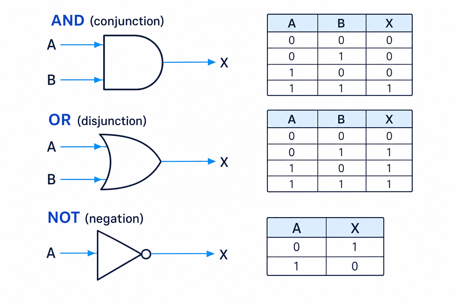
A logic gate is a diagram symbol that takes one or more Boolean inputs and produces one Boolean output.
Definition
Logic gate
A logic gate performs a Boolean operation on its input value or values, producing a single output value.
For OCR J277, you need to know three gates:
- AND, also called conjunction
- OR, also called disjunction
- NOT, also called negation
The symbols and truth tables below are worth learning carefully.
The AND gate
An AND gate outputs 1 only if all its inputs are 1.
| A | B | A AND B |
|---|---|---|
| 0 | 0 | 0 |
| 0 | 1 | 0 |
| 1 | 0 | 0 |
| 1 | 1 | 1 |
For example, a door might unlock only if:
- A = the card is valid
- B = the PIN is correct
The output is 1 only when both conditions are true.
Example
Using an AND gate
A door unlocks when cardValid AND pinCorrect is 1. Work out the output when cardValid = 1 and pinCorrect = 0.
- Match the inputs to the expression:
cardValidis 1, andpinCorrectis 0. - Apply the AND rule: AND only outputs 1 when both inputs are 1.
- Since one input is 0, the output is 0, so the door does not unlock.
The OR gate
An OR gate outputs 1 if at least one of its inputs is 1.
| A | B | A OR B |
|---|---|---|
| 0 | 0 | 0 |
| 0 | 1 | 1 |
| 1 | 0 | 1 |
| 1 | 1 | 1 |
For example, a warning light might turn on if:
- A = the temperature is too high
- B = the pressure is too high
Only one of these problems needs to be true for the warning light to turn on.
Tip
Remembering OR
OR is generous: if either input is 1, the output is 1. The only time OR outputs 0 is when all inputs are 0.
The NOT gate
A NOT gate has one input and reverses it.
| A | NOT A |
|---|---|
| 0 | 1 |
| 1 | 0 |
So if A is 1, NOT A is 0. If A is 0, NOT A is 1.
The NOT symbol is a triangle with a small circle at the output end. The small circle shows that the signal is being inverted.
Common Mistake
Forgetting NOT flips the value
NOT does not mean “not important” or “ignore this input”. It means change 1 to 0, or 0 to 1.
Truth tables
A truth table lists every possible combination of input values and shows the output for each combination.
Definition
Truth table
A truth table is a table that shows the output of a Boolean expression or logic diagram for every possible set of input values.
For two inputs, use four rows:
| A | B |
|---|---|
| 0 | 0 |
| 0 | 1 |
| 1 | 0 |
| 1 | 1 |
For three inputs, use eight rows. In general, for nnn inputs, the number of rows is 2n2^n2n.
When a logic diagram has more than one gate, it is usually easiest to add intermediate columns. These are extra columns for the outputs of gates before the final output.
Example
Completing a truth table with NOT and AND
Complete the truth table for the expression A AND NOT B.
- Start with all possible input combinations for A and B: 00, 01, 10, 11.
- Create an intermediate column for
NOT B, because B must be flipped before it is used in the AND gate. - Apply AND using A and
NOT B; the final output is 1 only where both of those columns are 1.
| A | B | NOT B | A AND NOT B |
|---|---|---|---|
| 0 | 0 | 1 | 0 |
| 0 | 1 | 0 | 0 |
| 1 | 0 | 1 | 1 |
| 1 | 1 | 0 | 0 |
Combining Boolean operators
You can combine gates to make more complex decisions. A combined logic diagram is read by following the wires from the inputs to the final output.
Here is a diagram for the expression Q = (A AND NOT B) OR C.
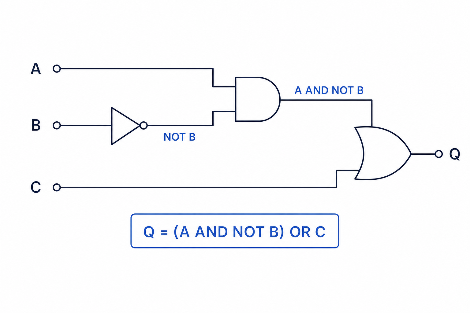
The expression has three stages:
- B is passed through a NOT gate, giving
NOT B. - A and
NOT Bgo into an AND gate, givingA AND NOT B. - That result is ORed with C, giving the final output Q.
Key Idea
Break combined diagrams into smaller signals
For multi-gate diagrams, do not try to solve everything at once. Label each intermediate output, then combine them one gate at a time.
Example
Completing a multi-gate truth table
Complete the truth table for Q = (A AND NOT B) OR C.
- List the eight input combinations for A, B and C, because there are three inputs and 23=82^3 = 823=8 rows.
- Work out
NOT Bfor each row by flipping B. - Work out
A AND NOT B; this is 1 only where A is 1 andNOT Bis 1. - Work out Q by ORing
A AND NOT Bwith C; Q is 1 if either of those values is 1.
| A | B | C | NOT B | A AND NOT B | Q |
|---|---|---|---|---|---|
| 0 | 0 | 0 | 1 | 0 | 0 |
| 0 | 0 | 1 | 1 | 0 | 1 |
| 0 | 1 | 0 | 0 | 0 | 0 |
| 0 | 1 | 1 | 0 | 0 | 1 |
| 1 | 0 | 0 | 1 | 1 | 1 |
| 1 | 0 | 1 | 1 | 1 | 1 |
| 1 | 1 | 0 | 0 | 0 | 0 |
| 1 | 1 | 1 | 0 | 0 | 1 |
Creating logic diagrams from scenarios
In exam questions, you may be given a scenario in words and asked to create, complete or edit a logic diagram or truth table.
A good method is:
- Identify each condition that can be true or false.
- Give each condition a clear input letter, such as A, B or C.
- Choose the correct gate:
- Use AND when all conditions must be true.
- Use OR when at least one condition must be true.
- Use NOT when a condition must be false.
- Combine gates step by step.
Example
Designing a security alarm diagram
An alarm should sound if the system is armed and the door is open, or if the panic button is pressed.
- Define the inputs: A = system armed, D = door open, P = panic button pressed.
- The phrase “system is armed and the door is open” means combine A and D with an AND gate:
A AND D. - The phrase “or if the panic button is pressed” means OR the previous result with P:
(A AND D) OR P. - The final output is
alarm = (A AND D) OR P, so the diagram needs an AND gate feeding into an OR gate.
Common Mistake
Treating everyday OR too loosely
In Boolean logic, OR means “one or the other or both”. So if A and B are both 1, A OR B is also 1.
Tip
Sanity-checking a truth table
Look at the final output column and ask whether it matches the story. For example, an AND condition should not output 1 unless all required inputs are 1.
Editing incomplete truth tables or diagrams
Sometimes a question gives you a partly completed diagram or truth table. You may need to fill in missing gates, wires or outputs.
Useful patterns:
- If the output is 1 only when both inputs are 1, the gate is AND.
- If the output is 1 when either input is 1, the gate is OR.
- If the output is always the opposite of the input, the gate is NOT.
If there are brackets in a Boolean expression, use them to decide which gates are connected first. For example, (A OR B) AND C is different from A OR (B AND C).
Common Mistake
Brackets can change the answer
Do not assume two expressions are the same just because they contain the same inputs and gates. The grouping of gates affects the final output.
Exam technique
In the exam
- For truth tables, add intermediate columns for each gate output before attempting the final column.
- For logic diagrams, follow the wires from left to right and label each intermediate signal.
- For scenarios, translate words carefully: and means AND, or means OR, and phrases like “not pressed” or “not valid” usually need NOT.
Self review
Check yourself
- What are the outputs of AND, OR and NOT for each possible input?
- How many rows would a truth table with three inputs need?
- How would you draw the logic for
Q = NOT A OR B?

Recap questions
Test yourself with 5 quick questions on this guide. Answer them all correctly to complete it.
You've reached the end
Test yourself on this topic, or move on to the next guide.
How was this guide?